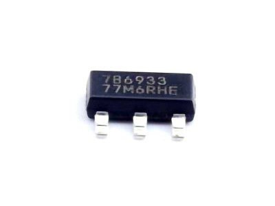
The TPS22919DCKR is a highly efficient load switch used for power management in various electronic devices. While it is a reliable component, like any electronic part, it may encounter issues that require troubleshooting. This article provides in-depth insights into common problems, their causes, and effective solutions to ensure optimal performance and longevity of the TPS22919DCKR.
TPS22919DCKR, troubleshooting, solutions, load switch, power management, electronics, device issues, common problems, power circuit, electronic components
Understanding the TPS22919DCKR and Common Troubleshooting Scenarios
The TPS22919DCKR is a popular load switch from Texas Instruments, designed to help manage power distribution across various parts of an electronic circuit. It is a part of the TPS22919 series of load switches, which are commonly used in mobile devices, consumer electronics, and industrial applications. These load switches help ensure efficient power delivery while protecting the rest of the circuit from power fluctuations or excessive current.
While the TPS22919DCKR is a robust and efficient component, it is not immune to common issues. Troubleshooting these issues often requires an understanding of both the device's functions and the typical failure points. In this part of the article, we will explore several frequent problems encountered with this load switch and the steps to identify and address them.
1. No Output Power: Causes and Solutions
One of the most common issues with the TPS22919DCKR is the failure to deliver output power. This can be frustrating, especially if the power input is functional. Here are several causes of this issue and their corresponding solutions:
Cause: Incorrect Enable Pin Voltage
The enable pin (often labeled as EN) controls the activation of the load switch. If this pin is not correctly driven, the device may fail to output power. The TPS22919DCKR requires the EN pin to be held at a logic-high level (typically 1.8V to 5.5V) for the device to turn on.
Solution: Check EN Pin Voltage
Ensure that the EN pin is being driven high by the controlling logic. A low voltage on the enable pin will result in the load switch being disabled, preventing any power from reaching the output. Use a multimeter or oscilloscope to measure the voltage at the EN pin and confirm it is within the recommended range.
2. Power Loss or Inconsistent Output Voltage
Another common problem is experiencing power loss or inconsistent output voltage. This can be caused by several factors, such as excessive current draw or incorrect wiring.
Cause: Overcurrent Protection Activation
The TPS22919DCKR has built-in overcurrent protection to prevent damage to the load switch and the connected circuit. If the output current exceeds the safe limit, the internal protection circuitry will shut down the switch, resulting in a power loss.
Solution: Verify Load Current
Check the current drawn by the load connected to the TPS22919DCKR. The device can handle up to 2.6A of continuous current, but exceeding this limit will trigger overcurrent protection. If the load requires more than the rated current, consider using a higher-rated switch or distributing the current load across multiple switches.
Cause: Incorrect Input Voltage
Inconsistent output voltage may also result from insufficient input voltage. The TPS22919DCKR requires a stable input voltage of at least 1.0V above the output voltage to function correctly.
Solution: Check Input Voltage
Ensure that the input voltage to the TPS22919DCKR is stable and within the specified range for the load switch. An unstable or low input voltage can cause the output voltage to fluctuate or drop entirely. Use an oscilloscope to observe the input voltage waveform for any irregularities.
3. Device Heating or Overheating
Overheating can be a serious issue with load switches. If the TPS22919DCKR becomes too hot, it may go into thermal shutdown mode to protect itself from damage.
Cause: Excessive Power Dissipation
High power dissipation due to excessive current draw or insufficient thermal management can cause the TPS22919DCKR to overheat. The device typically dissipates power in the form of heat, and if this heat is not properly managed, it can lead to thermal shutdown.
Solution: Improve Heat Dissipation
Ensure that the load switch has adequate heat dissipation. Consider using larger copper pads or a heat sink to help dissipate the heat more effectively. Additionally, verify that the PCB design includes proper thermal management, such as good grounding and efficient power routing.
4. Faulty or Damaged Circuitry
Another common reason for failure is the physical damage to the load switch or its supporting circuitry. While this can be more difficult to diagnose, it is still a possible cause of malfunction.
Cause: Damaged Pins or Traces
Over time, physical damage to the pins of the TPS22919DCKR or the traces on the PCB can result in unreliable behavior. This is often due to excessive heat, mechanical stress, or poor soldering during assembly.
Solution: Inspect the PCB
Visually inspect the PCB for any signs of damage or wear, such as burnt traces, broken pins, or damaged components. If the TPS22919DCKR is visibly damaged, replace the component with a new one. Ensure that the PCB design includes proper stress relief and good soldering techniques to avoid future damage.
Advanced Troubleshooting Tips and Solutions for TPS22919DCKR
While the most common troubleshooting issues are related to power delivery and overcurrent protection, there are more advanced troubleshooting scenarios that might arise with the TPS22919DCKR. This part will cover these more complex issues, provide detailed analysis, and offer solutions for ensuring the TPS22919DCKR operates optimally in your circuit.
1. Slow Turn-On or Turn-Off Behavior
In some cases, users might experience slow turn-on or turn-off of the TPS22919DCKR, which can lead to delays in power delivery or system response.
Cause: Capacitive Load or Long PCB Traces
A large capacitive load or excessively long PCB traces can cause slow turn-on or turn-off behavior in the load switch. The time it takes for the device to reach the desired voltage levels may be affected by the capacitance of the connected load or the parasitic capacitance in the traces.
Solution: Minimize Capacitive Load
Reduce the capacitance of the load connected to the output. Additionally, keep the PCB traces as short as possible between the load switch and the output to minimize parasitic effects. Use RC snubber circuits to help with transient response times.
2. Intermittent Functionality or Flickering Output
Intermittent functionality or flickering output can be caused by unstable voltage levels or improper power sequencing.
Cause: Power Sequencing Issues
The TPS22919DCKR may require proper power sequencing for optimal operation. If the power rails are not brought up or down in the correct order, the device may behave erratically, leading to flickering output.
Solution: Implement Proper Power Sequencing
Ensure that the input and output power rails are correctly sequenced according to the requirements of the TPS22919DCKR. Implementing a power sequencing circuit can help ensure that the power rails are stabilized before enabling the load switch.
3. Fault Pin Response Issues
The FAULT pin is an important feature of the TPS22919DCKR, as it provides an indication of fault conditions such as overcurrent, thermal shutdown, or undervoltage. If the FAULT pin is not behaving as expected, it may indicate a deeper issue with the device or the surrounding circuitry.
Cause: Fault Pin Wiring Issues
Incorrect wiring or a short circuit on the FAULT pin can result in abnormal behavior. If the pin is not properly connected or is exposed to noise, it can give false readings or fail to indicate actual faults.
Solution: Verify FAULT Pin Connections
Check the wiring and connection of the FAULT pin. Ensure that the pin is connected to the monitoring system and is not shorted or exposed to excessive noise. You can use an oscilloscope to observe the behavior of the FAULT pin and ensure it is reacting as expected to fault conditions.
4. Fault Diagnosis Using External Components
To further diagnose faults in the TPS22919DCKR, it can be helpful to use external diagnostic tools and components, such as current sense Resistors or oscilloscopes. These tools can give you more insight into the behavior of the load switch under various conditions.
Cause: Lack of Diagnostic Tools
Without the proper diagnostic equipment, it may be difficult to pinpoint issues like current spikes, voltage drops, or timing issues.
Solution: Use Current Sense Resistors and Oscilloscopes
Implement a current sense resistor in series with the load to monitor the current flow. This can help you identify if overcurrent protection is triggering prematurely. Additionally, using an oscilloscope to monitor the voltage waveforms at various points in the circuit can help identify timing or power delivery issues.
Conclusion
The TPS22919DCKR is a versatile and reliable load switch, but like any electronic component, it can encounter issues that affect its performance. By following the troubleshooting tips and solutions outlined in this article, you can ensure the optimal performance of the TPS22919DCKR and avoid potential problems in your circuit. Always refer to the manufacturer's datasheet for specific recommendations and guidelines, and ensure proper design practices for the most reliable and efficient operation of your load switch.
If you're looking for models of commonly used electronic components or more information about TPS22919DCKR datasheets, compile all your procurement and CAD information in one place.
( Partnering with an electronic component supplier ) sets your team up for success, ensuring that the design, production and procurement processes are streamlined and error-free. ( Contact us ) for free today

