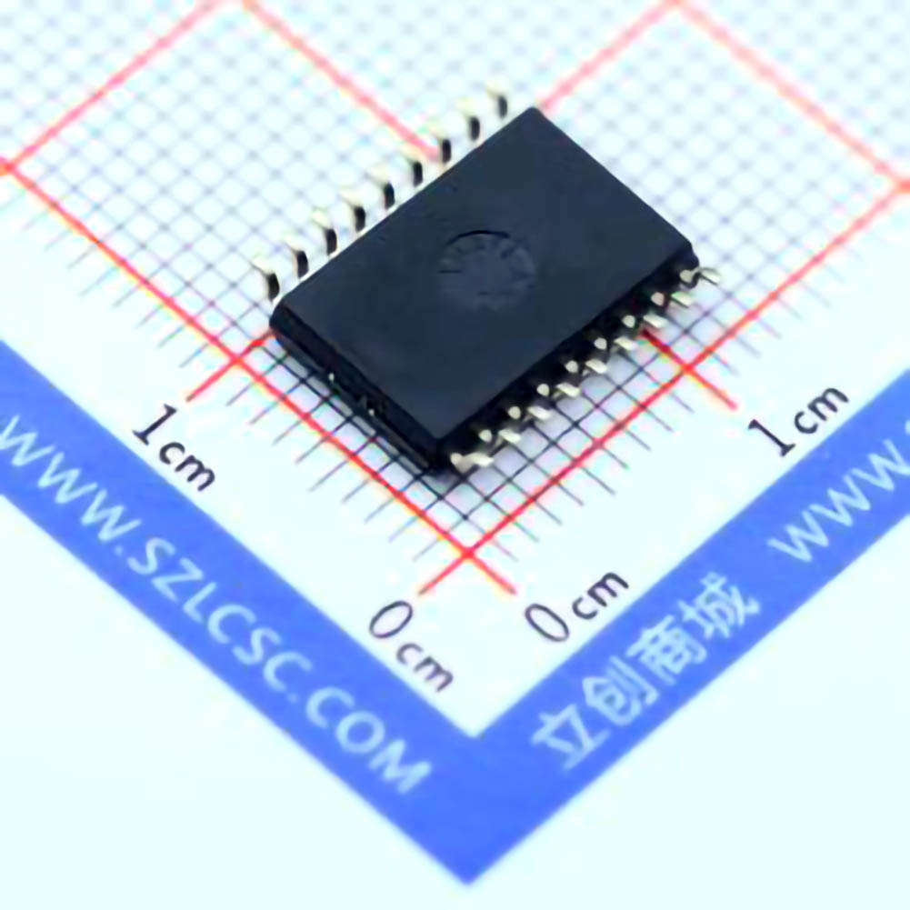
The Texas Instruments ULN2803ADWR is a popular Darlington transistor array used in various applications. This article explores the common troubleshooting techniques for the ULN2803ADWR, highlighting how to diagnose and fix issues to ensure optimal performance. Whether you're a hobbyist or a professional, this guide will help you quickly pinpoint problems and implement practical solutions.
ULN2803ADWR troubleshooting, Darlington transistor array, ULN2803ADWR common issues, troubleshooting guide, transistor failure, electronics troubleshooting, ULN2803ADWR repairs, common problems, component troubleshooting
Understanding the ULN2803ADWR and Its Common Issues
The ULN2803ADWR is an integrated circuit (IC) featuring seven Darlington transistor pairs designed for switching high-voltage or high-current loads with low-voltage logic. This chip is widely used in a variety of applications, from controlling motors and relays to driving LED s in automotive or industrial settings. While the ULN2803ADWR is known for its reliability, like any electronic component, it may experience issues over time. Troubleshooting this IC can save time and prevent costly replacements. In this part of the article, we'll discuss common problems associated with the ULN2803ADWR and how to diagnose them.
1.1. Overheating Issues
Overheating is one of the most common issues faced with the ULN2803ADWR. When the device operates beyond its specified temperature range, it can cause the transistors inside the chip to fail. This typically occurs when the load connected to the IC exceeds the current rating or when improper cooling is in place. Overheated components may lead to system failure or erratic behavior, especially in power-hungry applications.
Troubleshooting:
Step 1: Check the operating environment of the ULN2803ADWR. Ensure that the ambient temperature around the IC is within the recommended operating range (typically 0°C to 85°C).
Step 2: Measure the voltage and current supplied to the IC. Ensure that the load being driven does not exceed the current capacity of the individual transistors (500mA per channel).
Step 3: Use a heat sink or add ventilation to improve airflow and reduce the temperature.
1.2. Incorrect Output Behavior
Another frequent problem is the malfunctioning of the output pins, where they either do not switch on/off as expected or behave erratically. This could be due to several factors, such as incorrect wiring, a faulty input signal, or an issue with the IC’s internal components.
Troubleshooting:
Step 1: Double-check the input signal being sent to the ULN2803ADWR. Ensure that the voltage level is within the IC’s input requirements (typically between 2.4V to 5V for logic high).
Step 2: Measure the output pin voltages when the input is triggered. If no change is observed, suspect that the IC’s output drivers may be damaged.
Step 3: If necessary, replace the ULN2803ADWR or test the component in isolation on a breadboard to ensure the issue isn't caused by other circuit components.
1.3. Short Circuit Protection and Grounding Issues
Improper grounding or a short circuit on the output side of the ULN2803ADWR can lead to damage or failure of the chip. Short circuits often occur when the connected devices draw more current than the IC can handle, which in turn may result in internal damage to the transistors.
Troubleshooting:
Step 1: Inspect all connections for possible short circuits, especially between output pins and the ground.
Step 2: Check the external loads (such as motors, relays, or LEDs) for potential short circuits. Ensure that there are no exposed wires or incorrect connections.
Step 3: Test the ULN2803ADWR with no load connected and observe if the issue persists. If the issue resolves, the fault lies with the external components.
1.4. Faulty Inputs or Logic Level Issues
Since the ULN2803ADWR is designed to work with TTL or CMOS logic levels, issues with logic level inputs can cause malfunction. If the input voltage is too low or too high, the IC may not respond as expected. Inconsistent input logic can also cause the outputs to switch erratically.
Troubleshooting:
Step 1: Ensure that the input signal is within the acceptable voltage range for the IC, typically between 0V (logic low) and 5V (logic high).
Step 2: Use a logic analyzer or oscilloscope to verify the integrity of the input signal. Any noise or voltage fluctuations could indicate an issue with the signal source.
Step 3: If using CMOS logic, consider adding pull-up resistors to the inputs for better signal integrity.
Advanced Troubleshooting and Repair Tips for the ULN2803ADWR
While the common issues mentioned in Part 1 are easily identifiable and manageable with the right tools and knowledge, more advanced problems may require in-depth troubleshooting and repair strategies. This section dives deeper into those more intricate aspects, providing valuable tips for those looking to diagnose and fix more severe issues with the ULN2803ADWR.
2.1. Diagnosing Internal Transistor Failures
The ULN2803ADWR contains seven Darlington pairs, and one or more of these transistors could fail over time. Diagnosing transistor failure can be tricky because the IC might still appear functional under certain conditions, but with reduced performance or reliability.
Troubleshooting:
Step 1: Use a multimeter to check for shorts between the collector, emitter, and base terminals of the individual transistors within the IC. A short or open circuit between these terminals indicates that a transistor has failed.
Step 2: If possible, isolate the faulty transistor and check its operation by applying a known good input signal and observing the output.
Step 3: In some cases, it may be more cost-effective to replace the entire IC rather than attempting a complex repair on the internal components.
2.2. Testing the IC with External Loads
While the ULN2803ADWR may work fine with a small test circuit, it could fail when connected to actual external loads. Testing the IC with realistic load conditions is essential to ensure its reliability in real-world applications.
Troubleshooting:
Step 1: Apply a test load to each output channel of the ULN2803ADWR. This will simulate the actual operating conditions the IC will face in the final application.
Step 2: Use a power supply capable of delivering the necessary current, and monitor the voltage across the load and the IC’s output pins.
Step 3: Look for voltage drops or abnormal behavior under load. If the voltage drops significantly or the IC fails to switch, it might indicate a problem with the IC’s internal driver circuitry or that the load is too demanding for the current capacity of the IC.
2.3. External Components and Circuit Design
Sometimes, issues with the ULN2803ADWR stem from problems outside of the IC itself, such as issues with the external components in the circuit. Improperly chosen components or incorrect circuit design can affect the performance of the IC and lead to problems like erratic behavior or output failure.
Troubleshooting:
Step 1: Review the circuit schematic and ensure that all external components, such as resistors, diodes, and capacitors, are correctly rated for the application.
Step 2: Verify that flyback diodes are placed correctly if the IC is controlling inductive loads like motors or relays. Missing or incorrectly installed diodes can cause voltage spikes that damage the IC.
Step 3: Check for any impedance mismatches or signal interference that might disrupt the normal operation of the IC. Noise filters or additional decoupling capacitors might be necessary in certain designs.
2.4. Use of Alternative ICs and Replacement Strategies
If troubleshooting efforts do not resolve the issue, or if the ULN2803ADWR is damaged beyond repair, it may be necessary to consider replacing the IC. There are alternative Darlington transistor arrays available that can perform the same functions but may offer enhanced features, such as higher current ratings or more advanced protection circuits.
Troubleshooting:
Step 1: Identify any alternative ICs that could be compatible with your circuit design. Ensure that the replacement IC matches the pin configuration, input/output voltage levels, and current ratings of the ULN2803ADWR.
Step 2: Before replacing, ensure that all external components (e.g., resistors, diodes, capacitors) are also in good working condition. Replacing the IC alone might not solve the problem if other components are also faulty.
Step 3: Install the replacement IC and test the circuit thoroughly to ensure proper operation.
2.5. Preventive Maintenance and Best Practices
Preventive maintenance is key to ensuring the long-term reliability of the ULN2803ADWR and avoiding frequent troubleshooting. Following best practices in circuit design, component selection, and load management can greatly reduce the likelihood of issues arising.
Tips for Preventive Maintenance:
Tip 1: Always operate the ULN2803ADWR within its rated specifications for voltage, current, and temperature.
Tip 2: Implement proper heat dissipation methods (such as heat sinks and thermal pads) to avoid overheating.
Tip 3: Design circuits with appropriate filtering and protection to prevent voltage spikes or noise from affecting the IC.
Tip 4: Perform routine checks on your circuits to detect early signs of wear or failure, such as unusual temperature increases or erratic behavior.
By following these strategies, you can minimize downtime and extend the operational life of the ULN2803ADWR, ensuring reliable performance for your applications.
By understanding the common problems and advanced troubleshooting techniques outlined in this article, you should be equipped to tackle most issues with the ULN2803ADWR. Whether you're working on a DIY project or an industrial application, effective troubleshooting and maintenance will keep your circuits running smoothly for years to come.
If you're looking for models of commonly used electronic components or more information about ULN2803ADWR datasheets, compile all your procurement and CAD information in one place.
( Partnering with an electronic component supplier ) sets your team up for success, ensuring that the design, production and procurement processes are streamlined and error-free. ( Contact us ) for free today.

