Introduction to STGIPS10K60A and Common Troubleshooting Challenges
Introduction
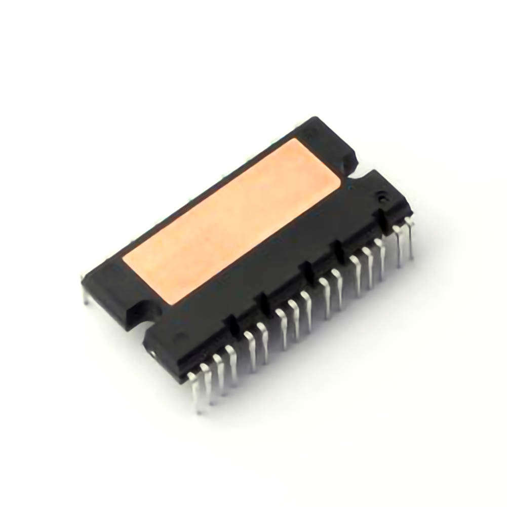
The STMicroelectronics STGIPS10K60A is an advanced integrated Power module designed for use in various high-power industrial applications such as motor drives, inverters, and power supplies. As a key component in modern power electronics, it integrates multiple functions into a single package, significantly reducing system complexity. The module contains an IGBT (Insulated Gate Bipolar Transistor), Diodes , gate drive circuitry, and protection features. Despite its robust design, engineers and technicians may encounter various operational issues that can affect system performance. This article aims to provide a comprehensive guide to troubleshooting common problems with the STGIPS10K60A and suggest practical solutions.
Understanding the STGIPS10K60A Module
The STGIPS10K60A integrates several critical elements necessary for high-efficiency power conversion, including:
IGBT (Insulated Gate Bipolar Transistor): Responsible for high-voltage switching in power applications.
Freewheeling Diode s: Used for recirculating current when the IGBT switches off.
Gate Driver: Manages the switching of the IGBT by controlling the gate voltage.
Protection Circuitry: Includes overcurrent, overvoltage, and thermal protection mechanisms.
Despite the compactness and efficiency of this module, various issues such as improper gate drive signals, Thermal Management problems, and faulty connections can cause system malfunction. Below, we’ll discuss some of the most common troubleshooting challenges encountered during the operation of the STGIPS10K60A.
1. Overheating and Thermal Management Issues
One of the most common issues faced when using the STGIPS10K60A is overheating. Given the high power levels these modules handle, improper thermal management can lead to overheating, which in turn may cause damage to the internal components, resulting in failure.
Causes of Overheating:
Insufficient Heat Sink: The heat generated by the IGBT may not dissipate adequately if the module is not equipped with an appropriate heatsink.
High Ambient Temperature: Operating the module in an environment with a high ambient temperature can hinder heat dissipation.
Excessive Switching Losses: Improper switching frequency or load conditions can increase power losses in the IGBT, leading to excess heat generation.
Solutions:
Use an Adequate Heat Sink: Ensure that the module is paired with a heat sink that has the necessary thermal conductivity to dissipate heat effectively. The STGIPS10K60A typically comes with a recommended heat sink in the datasheet.
Improve Airflow: Increase airflow around the module to enhance cooling. Using forced-air cooling systems can reduce thermal buildup.
Monitor Power Dissipation: Evaluate switching frequency and load conditions to ensure they are within the optimal operating range. Reducing switching frequency in high-load conditions can minimize excessive power dissipation.
2. Gate Drive Circuit Failures
The gate driver is an essential component for the proper operation of the STGIPS10K60A. It ensures that the gate of the IGBT receives the correct voltage signals, enabling it to switch on and off efficiently. Gate drive failures can lead to incomplete switching, excessive heat generation, and reduced efficiency.
Causes of Gate Drive Failures:
Incorrect Gate Drive Voltage: If the gate voltage is insufficient or too high, the IGBT may fail to turn on or off completely, leading to high switching losses.
Faulty Gate Driver IC: The gate driver IC can sometimes fail due to electrical overstress, resulting in irregular switching behavior.
Grounding Issues: Improper grounding of the gate driver can lead to erratic behavior and malfunction.
Solutions:
Verify Gate Drive Voltages: Ensure that the gate drive voltages are within the specifications provided in the datasheet. A typical IGBT requires a gate- EMI tter voltage of approximately 15V for turning on.
Check Gate Driver IC: Inspect the gate driver IC for signs of damage or malfunction. If necessary, replace the faulty gate driver with a new component.
Inspect Ground Connections: Ensure all ground connections are secure and properly configured to avoid noise and instability in the gate drive signal.
3. Voltage Spikes and Overvoltage Protection
Voltage spikes are another common issue encountered in power electronics systems. These spikes can occur when switching inductive loads, leading to high transient voltages that could damage the IGBT or other components within the module.
Causes of Voltage Spikes:
Inductive Load Switching: When switching off inductive loads, such as motors or transformers, the collapsing magnetic field can generate high voltage spikes.
Lack of Snubber Circuit: Without a snubber circuit or clamping diode to absorb the energy from the voltage spike, these transients can cause damage to the power module.
Poor PCB Layout: A poor layout that leads to parasitic inductances can exacerbate voltage spikes.
Solutions:
Use a Snubber Circuit: Implementing a snubber circuit across the IGBT can help suppress voltage spikes caused by inductive loads. A snubber usually consists of a resistor and capacitor combination to dissipate the energy generated during switching.
Install a Clamping Diode: A flyback diode (or freewheeling diode) can provide a safe path for current during switching, reducing the chance of voltage spikes.
Optimize PCB Layout: Ensure the PCB layout minimizes parasitic inductance and resistance, which can exacerbate voltage transients.
4. Overcurrent Protection Activation
The STGIPS10K60A module includes overcurrent protection to prevent damage in case of excessive current. However, false triggering of overcurrent protection can be a significant problem, leading to unnecessary system shutdowns.
Causes of Overcurrent Protection Activation:
Inrush Current: At power-on, inrush current due to capacitive charging can trigger the overcurrent protection circuit.
Incorrect Current Sensing: Faulty current sensing circuits or components can lead to false overcurrent detection.
Motor Stall or Short Circuit: A motor stall or short-circuit condition can cause a real overcurrent, but distinguishing between real and false overcurrent events can sometimes be challenging.
Solutions:
Inrush Current Limiting: Use soft-start circuits or pre-charge circuits to limit inrush current at power-up.
Verify Current Sensing Circuit: Inspect the current sensing components for accuracy. Calibration of the current sensors can also help prevent false overcurrent detection.
Check Load Conditions: Ensure that the connected load (e.g., a motor) is not operating under excessive stress or facing a stall condition that could trigger the overcurrent protection.
Advanced Troubleshooting and Solutions for STGIPS10K60A
5. Short Circuit Protection and Fault Diagnostics
The STGIPS10K60A features integrated short circuit protection to prevent catastrophic failures due to short circuits in the power stage. However, false triggers or insufficient protection can still occur under certain conditions.
Causes of Short Circuit Protection Issues:
False Short Circuit Detection: Over-sensitive protection circuitry might trigger false alarms, causing unnecessary shutdowns.
External Short Circuit: An actual external short circuit in the load can lead to the activation of the protection features.
Poor PCB Layout or Component Failure: A malfunction in PCB components or a poor layout may affect the protection circuit’s functionality.
Solutions:
Ensure Proper Fault Diagnostics: Regularly monitor fault signals from the module. Many modules, including the STGIPS10K60A, provide diagnostic outputs that can help pinpoint the exact cause of a fault.
Check External Connections: Inspect the connections to ensure there are no shorts in the external circuits connected to the module.
Review Layout and Component Selection: Make sure the PCB layout adheres to the recommended guidelines and that all components, especially resistors and Capacitors , are correctly rated.
6. Noise and EMI Issues
Electromagnetic interference (EMI) and noise can be a significant problem when working with high-power devices like the STGIPS10K60A. These issues can cause operational instability and affect the performance of other sensitive equipment nearby.
Causes of EMI:
High-Frequency Switching: The fast switching of the IGBT can generate high-frequency noise that radiates from the module.
Insufficient Shielding: Poor shielding or lack of grounding can allow EMI to propagate through the system.
Unoptimized PCB Layout: Long, unshielded traces or inadequate grounding can act as antenna s, generating EMI.
Solutions:
Use Proper Shielding: Incorporate shielded enclosures or metal casings around the module to minimize EMI propagation.
Improve PCB Grounding: Ensure that the PCB has a solid ground plane to reduce noise and prevent EMI from affecting sensitive components.
Use Snubber Circuits: Snubber circuits not only suppress voltage spikes but also help to reduce high-frequency noise generated by switching.
7. PCB Design and Layout Considerations
A critical factor in ensuring the long-term reliability and performance of the STGIPS10K60A is proper PCB design and layout. A poorly designed PCB can exacerbate issues like noise, parasitic inductances, and voltage spikes.
Key Layout Considerations:
Minimize Parasitic Inductance: Keep the power traces as short and wide as possible to reduce parasitic inductance.
Good Grounding Practices: Use a solid, low-impedance ground plane to minimize noise and ensure proper functioning of the gate driver.
Decoupling Capacitors: Place decoupling capacitors as close as possible to the power pins of the module to filter high-frequency noise and stabilize the voltage supply.
8. Conclusion
The STGIPS10K60A is an incredibly efficient and reliable power module, but, like any electronic component, it can encounter issues that require troubleshooting and corrective action. By understanding the potential causes of common problems such as overheating, gate drive failure, voltage spikes, overcurrent activation, and EMI, engineers can apply the appropriate solutions to restore performance. Proper PCB design and layout practices also play a critical role in preventing these issues from occurring in the first place. By addressing these challenges systematically, users can ensure the longevity and reliability of their STGIPS10K60A-based systems, leading to more efficient and stable operations.
If you're looking for models of commonly used electronic components or more information about STGIPS10K60A datasheets, compile all your procurement and CAD information in one place.
(Partnering with an electronic component supplier) sets your team up for success, ensuring that the design, production and procurement processes are streamlined and error-free. (Contact us) for free today


