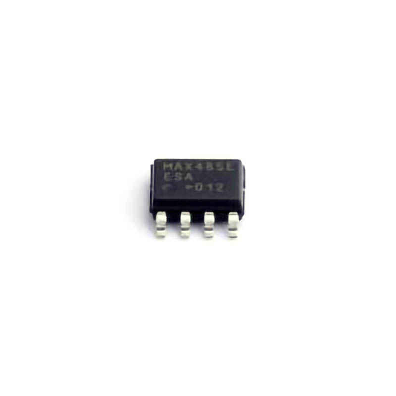
The ADI/MAXIM MAX485EESA +T is a highly efficient and versatile RS-485 transceiver used in many industrial, automotive, and communication applications. This article provides a detailed guide to common troubleshooting methods and solutions to ensure the reliable operation of the MAX485EESA+T . Whether you're working with serial communication systems or embedded projects, understanding how to address potential issues can greatly improve the performance and longevity of your systems.
MAX485EESA+T, RS-485 transceiver, troubleshooting, communication systems, industrial applications, embedded systems, data transmission, electronics troubleshooting, MAX485 solutions
Understanding the MAX485EESA+T and Its Common Issues
The MAX485EESA+T is an essential component in many data communication systems, especially in industrial environments where reliable data transmission is critical. This IC is a low- Power transceiver designed to facilitate communication in systems that use the RS-485 standard, a common protocol in long-distance and noisy industrial settings.
The MAX485EESA+T provides the necessary interface between microcontrollers or other data sources and the communication bus, handling both transmitting and receiving data over long distances. However, like any complex electronic component, users may encounter several issues while using this chip. In this article, we’ll take a look at common problems associated with the MAX485EESA+T and discuss effective solutions to fix or prevent them.
1. Poor Signal Integrity
One of the most frequent issues with RS-485 communication systems using the MAX485EESA+T is poor signal integrity. This can lead to data corruption, garbled transmission, or complete communication failure. Poor signal quality often arises due to improper wiring, long cable runs, or mismatched impedance.
Possible Causes:
Inadequate termination resistance: RS-485 networks require termination resistors at both ends of the transmission line to minimize signal reflections. If these resistors are not present or are incorrectly sized, it can lead to signal distortion.
Improper grounding: RS-485 is sensitive to noise, and inadequate grounding of the system can cause interference, leading to data errors.
Solutions:
Proper termination: Ensure that termination resistors (typically 120Ω) are placed at both ends of the RS-485 bus. This is essential for preventing signal reflections and ensuring the transmission integrity.
Ensure proper grounding: Use a single-point grounding system to avoid ground loops, which can introduce noise. If possible, use a shielded cable to further protect the signals.
2. Low or High Voltage Levels
The MAX485EESA+T operates within specific voltage ranges to communicate effectively with the system it’s connected to. Voltage levels that are too low or too high can prevent the chip from operating properly, leading to intermittent issues or a complete failure in communication.
Possible Causes:
Incorrect power supply voltage: The MAX485EESA+T requires a 5V power supply. If the voltage is too low or unstable, the transceiver may fail to power up, or it may behave erratically.
Mismatched logic levels: RS-485 systems use differential voltage signals. If the voltage levels are incorrect, the system may not correctly interpret the transmitted signals.
Solutions:
Verify the power supply: Ensure that the MAX485EESA+T is powered by a stable 5V source. If you're using a power regulator, check that the output voltage is within tolerance.
Check voltage levels: Use an oscilloscope or a multimeter to measure the voltage levels on the RS-485 data lines. Ensure that the voltage differences fall within the acceptable range for RS-485 communication, typically between -7V and +12V.
3. Bus Contention or Signal Conflicts
RS-485 supports multiple devices on the same bus. However, if multiple devices attempt to drive the bus simultaneously, bus contention can occur, leading to data loss or transmission errors. This issue can happen if multiple drivers are enabled at the same time or if the bus is not properly managed.
Possible Causes:
Multiple drivers active: If more than one transceiver on the bus is configured to transmit data simultaneously, it can cause a conflict, leading to signal distortion.
Improper direction control: The MAX485EESA+T requires the DE (Driver Enable) and RE (Receiver Enable) pins to be properly managed to avoid contention. If these pins are not correctly controlled, the transceiver might be in an invalid state, either transmitting while it should be receiving, or vice versa.
Solutions:
Ensure correct pin control: Use microcontroller pins to control the DE and RE pins. Make sure that only one device is allowed to transmit at any given time. You can implement a mechanism to control the direction and ensure that when one device is transmitting, others are in a receiving mode.
Use bus arbitration: If your system design involves multiple transmitters, consider implementing a protocol to manage when each device can transmit, or use a master-slave configuration to avoid conflicts.
Advanced Troubleshooting for MAX485EESA+T
4. Inconsistent Data Transmission
Another common issue users face is inconsistent data transmission, where the data may be partially received or garbled. This can be especially frustrating as the problem can arise sporadically, making it hard to pinpoint the cause.
Possible Causes:
Noise and interference: Long cable runs or noisy environments can introduce interference that distorts the data signals.
Incorrect baud rate or mismatched settings: RS-485 communication relies on precise timing, and if the baud rate or other communication settings (such as parity or stop bits) are mismatched between devices, data transmission can become unreliable.
Inadequate decoupling: Insufficient decoupling capacitor s on the power supply or data lines can lead to noise and inconsistent signals.
Solutions:
Shielded cables: Use twisted pair cables or shielded cables to reduce noise pickup, especially in environments with high electromagnetic interference ( EMI ).
Baud rate synchronization: Verify that all devices on the RS-485 network are set to the same baud rate, parity, stop bits, and other communication parameters.
Add decoupling capacitors: Place a 0.1µF ceramic capacitor between the VCC and GND pins of the MAX485EESA+T, close to the device, to filter out high-frequency noise and improve signal stability.
5. Overheating and Power Dissipation
Another issue that might arise with the MAX485EESA+T is overheating. While the device is designed to operate at low power, excessive current draw or improper power supply can cause the chip to overheat, potentially leading to failure or reduced performance.
Possible Causes:
Excessive current draw: If the power supply is not correctly regulated, the chip may draw more current than it can handle, leading to overheating.
Inadequate heat sinking: If the device is located in an enclosed or poorly ventilated area, heat can build up, causing the chip to overheat.
Solutions:
Ensure proper current regulation: Use a stable power supply and check that the MAX485EESA+T is drawing power within its specified range. If necessary, use a current-limiting power source to avoid overcurrent conditions.
Improve ventilation: Ensure adequate airflow around the device. If the circuit board is enclosed, consider using heat sinks or improving the enclosure design to allow for better thermal dissipation.
6. Pin Function Misunderstanding
The MAX485EESA+T has multiple pins that control its functionality. Users sometimes encounter issues due to misunderstanding or incorrect wiring of these pins, particularly the DE (Driver Enable), RE (Receiver Enable), and RO (Receiver Output) pins.
Possible Causes:
Improper connection of control pins: If the DE or RE pins are not correctly wired, the transceiver may not function as expected.
Incorrect use of RO: The RO pin is used to read received data. If this pin is connected incorrectly or not used properly in the circuit, data may not be transmitted correctly.
Solutions:
Refer to the datasheet: Carefully read the MAX485EESA+T datasheet and ensure that all pins are correctly connected and configured. Double-check your wiring to ensure the DE and RE pins are controlled properly and that the RO pin is properly used for receiving data.
Conclusion
The MAX485EESA+T is a reliable and widely used RS-485 transceiver, but like any component, it requires proper setup and troubleshooting when issues arise. From poor signal integrity to incorrect voltage levels, the key to resolving common problems lies in understanding the root causes and applying the right solutions. By following the tips outlined in this guide, you can ensure that your MAX485EESA+T operates smoothly and efficiently, avoiding many of the common pitfalls that users encounter. Always remember to verify connections, check voltage levels, and use proper grounding techniques for a more reliable communication system.
If you're looking for models of commonly used electronic components or more information about MAX485EESA+T datasheets, compile all your procurement and CAD information in one place.
( Partnering with an electronic component supplier) sets your team up for success, ensuring that the design, production and procurement processes are streamlined and error-free. (Contact us) for free today.


