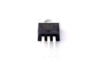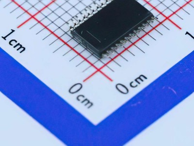
The MCP3421A0T-E/CH is a versatile 18-bit Analog-to-Digital Converter (ADC) used in various applications for high-precision data acquisition. However, like all electronic components, users may encounter issues during its integration and operation. This article explores common troubleshooting tips and solutions for MCP3421A0T-E/CH, providing engineers, hobbyists, and designers with practical insights to resolve typical problems.
MCP3421A0T-E/CH, troubleshooting, solutions, Analog-to-Digital Converter, MCP3421 issues, ADC problems, electronics troubleshooting, sensor data acquisition, precision measurement
Understanding the MCP3421A0T-E/CH and Common Issues
The MCP3421A0T-E/CH is a high-precision 18-bit ADC manufactured by Microchip Technology. This ADC is commonly used in applications requiring high-resolution analog-to-digital conversion, such as sensor interfacing, data logging, and measurement systems. The key features of the MCP3421A0T-E/CH include its differential input, programmable resolution, and low-power consumption, making it an excellent choice for portable and battery-powered devices.
However, users often face a range of issues during its integration into systems. This section will address the most common problems and guide you on how to resolve them efficiently.
1. Power Supply Issues
One of the most frequent causes of problems when using the MCP3421A0T-E/CH is issues related to the power supply. The ADC requires a stable voltage supply to operate correctly, typically ranging from 2.7V to 5.5V.
Symptoms of Power Supply Issues:
Inconsistent or erratic ADC readings.
The device fails to initialize or respond to commands.
The device may produce no output, or the output may be noisy.
Solutions:
Check the Power Source: Ensure that the power supply voltage falls within the specified range (2.7V to 5.5V). Power supplies that fluctuate or provide voltages outside of this range can cause unpredictable behavior.
Use Decoupling Capacitors : Place a 0.1µF ceramic capacitor close to the power pins (VDD and VSS) of the MCP3421 to filter out high-frequency noise. A 10µF electrolytic capacitor may also be added for additional stability, especially when using batteries.
Verify Ground Connections: Ensure that the ground (VSS) is securely connected and is at the same potential as the system’s ground. A floating ground can lead to noise and erratic readings.
2. Improper Initialization
Another common problem with the MCP3421 is improper initialization, especially when configuring the ADC settings via the I2C interface. Users often overlook specific configuration bits that can cause the ADC to operate incorrectly.
Symptoms of Improper Initialization:
The MCP3421 may not start the conversion process after receiving a command.
The device does not produce any output data, or the data seems incorrect.
Communication over I2C is unsuccessful, or the MCP3421 is not responding.
Solutions:
Review the Initialization Code: Ensure that the I2C commands sent to the MCP3421 match the device's datasheet. The MCP3421 requires specific bits to be set in the control register to initiate a conversion or configure the resolution. Double-check that the appropriate address is used and that the start/stop conditions are correct.
Start Conversion Correctly: After configuring the ADC's settings, ensure that a valid start conversion command is issued. Missing or incorrect conversion initiation commands will prevent data from being read.
3. Noise and Signal Interference
In many sensor applications, signal noise is a significant problem, particularly when the MCP3421 is used in noisy environments or in long-distance sensor wiring.
Symptoms of Noise and Signal Interference:
Unstable or fluctuating ADC readings.
Measurements are significantly off from the expected values.
High levels of digital noise in the signal.
Solutions:
Shielding: Use proper shielding around the MCP3421 and its input lines, especially if they are exposed to high-frequency electromagnetic interference (EMI) from nearby digital devices or power circuits.
Twisted-Pair Cables: Use twisted-pair cables for long analog signal lines to minimize noise pickup.
Analog Filtering: Implement low-pass filtering on the input signal to remove high-frequency noise. An RC filter can be used to smooth out the signal before it reaches the ADC input.
I2C Bus Integrity: If I2C communication is used for configuration and data retrieval, ensure that the I2C lines (SCL and SDA) are properly terminated and have pull-up Resistors to prevent data corruption.
4. Resolution and Sampling Rate Conflicts
The MCP3421 provides selectable resolutions ranging from 18 bits to 12 bits, with corresponding sampling rates that decrease as resolution increases. A common issue arises when users select a resolution that is too high for their application, leading to slower sampling rates that may not meet the needs of real-time systems.
Symptoms of Resolution and Sampling Rate Conflicts:
The ADC is too slow for the required sampling rate.
Data is missed or arrives too late for processing.
The system’s performance is compromised due to low sampling rates at high resolutions.
Solutions:
Match Resolution to Application Needs: If your application does not require 18-bit resolution, consider using a lower resolution setting. For example, reducing the resolution to 12 bits can dramatically increase the sampling rate, providing real-time performance for fast-changing signals.
Adjust Sampling Rate Settings: Carefully choose the resolution and sampling rate that align with your application’s time constraints. The MCP3421 allows users to adjust both, so take advantage of these settings to find a balance between resolution and speed.
5. Incorrect Input Voltage Range
The MCP3421 is designed for differential inputs, but users may sometimes apply common-mode voltages that exceed the specified range, leading to incorrect measurements or even damage to the device.
Symptoms of Incorrect Input Voltage Range:
The output of the MCP3421 is saturated at the upper or lower end of the voltage range.
The ADC produces erroneous readings or no output at all.
The device may overheat or show signs of electrical stress.
Solutions:
Ensure Proper Input Voltage Range: The MCP3421’s differential input range is typically from VSS to VDD. Be sure that the input signal stays within this range. Any voltage outside of this range can result in undefined behavior.
Use Level Shifting Circuits: If your input signals are not within the allowed voltage range, use level shifters or op-amps to ensure that the input voltage is within the MCP3421’s specification.
Advanced Troubleshooting and Techniques for MCP3421A0T-E/CH
Now that we’ve covered the most common issues encountered with the MCP3421A0T-E/CH, let’s explore more advanced troubleshooting techniques that can help in diagnosing and resolving less common problems. These strategies will help you ensure that the MCP3421 is functioning optimally and meeting the needs of your application.
6. I2C Communication Problems
I2C communication is the primary method for configuring the MCP3421 and retrieving data. However, several factors can interfere with successful I2C communication.
Symptoms of I2C Communication Problems:
The MCP3421 is not responding to I2C commands.
Data transfer over I2C is corrupted or inconsistent.
The system experiences communication timeouts.
Solutions:
Check I2C Clock Speed: Ensure that the I2C clock speed is within the MCP3421’s capabilities. Higher clock speeds might cause data corruption or missed commands. The MCP3421 operates at I2C speeds up to 400kHz, but reducing the clock speed to 100kHz can sometimes resolve communication issues.
Check Pull-up Resistors: I2C communication requires pull-up resistors on the SDA and SCL lines. If these are missing or improperly sized, it can cause slow or unreliable communication. Standard pull-up resistors (typically 4.7kΩ) should be used for both lines.
Check for Address Conflicts: Ensure that the MCP3421’s I2C address is correctly set. The default address for the MCP3421 is 0x68, but this can be changed by modifying the address pins (A0, A1, A2). Conflicts with other I2C devices on the same bus can lead to communication failures.
7. Handling Data Overflow
The MCP3421 offers high-resolution conversions, but with high precision comes the potential for overflow or out-of-range readings if the input signal exceeds the ADC’s full-scale range.
Symptoms of Data Overflow:
The ADC output values are clamped to the upper or lower limits (e.g., 0xFFFF for 18-bit data).
Readings show the same maximum or minimum value regardless of input variations.
Solutions:
Use Input Scaling: Ensure that your input signals are scaled to match the ADC’s range. If the input voltage exceeds the full-scale range, consider using external attenuation circuits to reduce the signal amplitude.
Monitor Output Range: Always check the MCP3421’s output range and compare it with the expected result. If you’re using high-resolution settings, ensure that the input signal can occupy the full dynamic range of the ADC.
8. Temperature Effects
Temperature variations can affect the performance of the MCP3421, especially in high-precision applications. Overheating can cause inaccurate readings, noise, and even device failure if left unchecked.
Symptoms of Temperature Effects:
Inconsistent readings or drift in ADC output over time.
Significant differences in measurements when the temperature changes.
Solutions:
Use a Temperature Compensation Algorithm: Implement temperature compensation in your software if the MCP3421 is operating in a thermally unstable environment. Some systems use temperature sensors to adjust ADC readings for thermal variations.
Ensure Proper Ventilation: If the device is used in a high-power system, ensure that there is sufficient airflow to prevent overheating. Additionally, check for any heat sources nearby that could affect the device’s temperature.
9. Output Calibration
Even with high-quality ADCs like the MCP3421, calibration may still be required for some applications to ensure that the ADC output matches the actual measured values.
Symptoms of Output Calibration Problems:
The conversion results are consistently off from the expected value.
Small measurement errors accumulate over time.
Solutions:
Perform Factory Calibration: The MCP3421 may require factory calibration for the highest accuracy, especially when used in critical measurement systems. However, you can calibrate the device in the field by applying known reference voltages to the input and adjusting the software to correct for any offset or gain errors.
Regular Calibration: For systems where the highest accuracy is required, implement a regular calibration schedule to ensure that the ADC maintains its precision over time.
Conclusion
The MCP3421A0T-E/CH is a powerful tool for high-precision measurement and data acquisition. By understanding common troubleshooting strategies, power management, signal integrity, and other potential issues, users can integrate the ADC into their designs effectively. Employing these tips and solutions will help to ensure reliable and accurate operation, making the MCP3421 a valuable component in your electronic systems.
Partnering with an electronic components supplier sets your team up for success, ensuring the design, production, and procurement processes are quality and error-free.

