Common ATMEGA128A-MU Issues and Effective Solutions
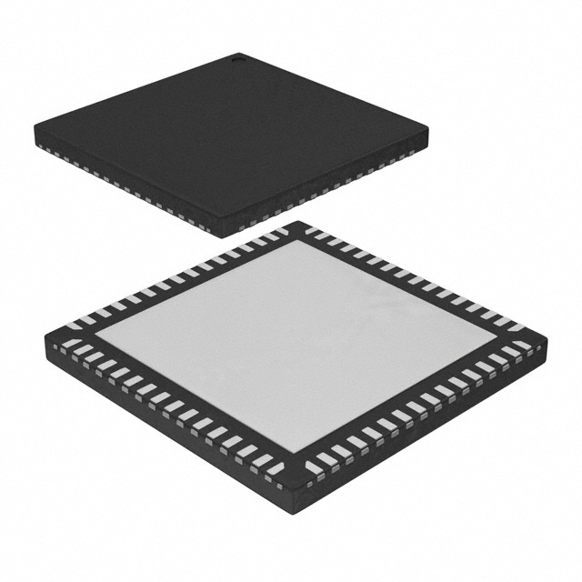
The Microchip Technology ATMEGA128A-MU is a widely used microcontroller from the AVR family, renowned for its versatility, performance, and low Power consumption. However, like any piece of electronics, users may encounter issues during development or operation. Troubleshooting these problems requires a thorough understanding of the microcontroller's behavior, common faults, and their corresponding solutions.
1. Microcontroller Not Responding to Code Uploads
One of the most common issues users face with the ATMEGA128A-MU is failure to upload code. This can be incredibly frustrating, especially when everything seems set up correctly.
Possible Causes:
Incorrect Programmer Configuration: The programmer interface might be set up incorrectly in the IDE (Integrated Development Environment).
Faulty USB Connection: A poor or faulty connection between the programmer and the ATMEGA128A can disrupt the upload process.
Wrong Fuse Settings: Incorrect fuse settings can prevent the microcontroller from entering the proper bootloader mode or disable Communication interfaces like SPI or UART.
Solutions:
Check Programmer Interface: Make sure that the programmer (e.g., USBasp or USBtiny) is correctly configured in your IDE. Double-check that the programmer type and communication interface (e.g., SPI or JTAG) match your setup.
Test the USB Cable and Port: Try using a different USB cable and ensure that the port is not malfunctioning. Consider using a USB hub or a direct connection to the PC to eliminate potential issues.
Verify Fuse Settings: Use tools like avrdude to read the current fuse settings and verify that they are correctly set for your intended operation. If necessary, reset the fuses using the programmer.
2. Power Supply Issues
Power supply issues are common with microcontrollers, and the ATMEGA128A-MU is no exception. Improper or insufficient power can lead to erratic behavior or total failure to operate.
Possible Causes:
Unstable Power Source: A fluctuating or insufficient voltage supply can cause the microcontroller to behave unpredictably.
Incorrect Voltage Levels: The ATMEGA128A operates at 5V, and applying too high or too low a voltage can result in malfunction.
Solutions:
Use a Stable Power Source: Ensure that the microcontroller is powered by a stable and regulated 5V supply. You may want to consider using a dedicated voltage regulator for critical projects.
Measure Voltage Levels: Use a multimeter to measure the voltage supply to the microcontroller to ensure it is within the acceptable range (typically 4.5V to 5.5V).
Decouple Power: Add decoupling capacitor s close to the power supply pins to filter out noise and improve the stability of the power supply.
The ATMEGA128A relies heavily on accurate clock timing, especially for applications like communication protocols or time-sensitive tasks. Clock-related issues can manifest in a variety of ways, such as timing discrepancies or failure to communicate with peripherals.
Possible Causes:
Incorrect Clock Source Selection: If the microcontroller is set to use the wrong clock source (internal vs. external), it may cause timing issues.
Clock Oscillator Failure: The external crystal oscillator may not be functioning properly, leading to clock instability.
Solutions:
Check Clock Source Configuration: In the fuse settings, verify that the correct clock source is selected (e.g., external crystal oscillator or internal RC oscillator).
Test the Oscillator: If using an external crystal, check the connections and ensure that the oscillator circuit is functioning. You can measure the output with an oscilloscope to check for a proper signal.
Reconfigure Clock Settings: If the clock source is incorrect, use a programmer to modify the fuse settings and restore the correct clock configuration.
Advanced Troubleshooting for ATMEGA128A-MU and Solutions
After resolving the more common issues, developers may encounter more advanced problems with the ATMEGA128A-MU. These problems often require a deeper understanding of the microcontroller’s internal workings, including Memory , communication, and peripheral interactions.
4. Peripheral Communication Failure
When interfacing with peripherals such as sensors, displays, or motors, communication problems can occur. These issues can be due to improper initialization, incorrect protocol settings, or electrical issues.
Possible Causes:
Incorrect Baud Rate or Protocol Settings: When communicating via protocols like UART, SPI, or I2C, setting an incorrect baud rate or protocol configuration can result in failed communication.
Pin Configuration Issues: Misconfigured pins (e.g., setting a pin as an output when it should be an input) can prevent correct communication.
Solutions:
Double-Check Protocol Configuration: Verify that the baud rate, data bits, stop bits, and parity are correctly set for UART communication. Similarly, ensure that SPI and I2C communication settings (clock speed, master/slave mode) are correct.
Ensure Proper Pin Mapping: Consult the ATMEGA128A datasheet for accurate pin configurations for peripherals. Check that the correct pins are assigned to the communication interface and that they are configured as inputs or outputs as required.
Use Debugging Tools: Use a logic analyzer or oscilloscope to monitor the communication lines (TX, RX, SCL, SDA, etc.) to ensure that data is being transmitted correctly.
5. Memory Overflow and Corruption
Memory-related problems can cause significant issues in microcontroller-based applications. For the ATMEGA128A-MU, problems like stack overflow or corrupted flash memory may occur during development.
Possible Causes:
Stack Overflow: The stack may overflow if the microcontroller is running complex recursive functions or handling large data structures without sufficient memory.
Flash Memory Corruption: If the program is writing to flash memory or EEPROM during runtime, improper handling can lead to corruption.
Solutions:
Optimize Memory Usage: Reduce the use of large local variables, especially in recursive functions, and ensure that buffers are properly sized. Consider using dynamic memory allocation cautiously.
Enable Stack Checking: Use the stack pointer to check for stack overflow. The ATMEGA128A includes a stack pointer register, which can be monitored to prevent overflow.
Careful Flash Memory Access : Avoid writing to the flash memory during runtime unless necessary. If using EEPROM, ensure that write cycles do not exceed their rated limits.
6. Device Reset and Brown-Out Detection
In some cases, the ATMEGA128A-MU may unexpectedly reset or behave erratically due to power fluctuations or external conditions. This could be related to the brown-out detection feature or improper handling of reset conditions.
Possible Causes:
Brown-Out Detection (BOD): If the power supply dips below a certain threshold, the brown-out detection feature will reset the microcontroller to prevent malfunction.
External Reset Issues: An external reset pin (if used) might be triggered erroneously due to noise or a wiring issue.
Solutions:
Check Brown-Out Threshold: In the fuse settings, ensure that the brown-out detection threshold is correctly set for your application. If you are confident in the stability of your power supply, you can disable or adjust the threshold for BOD.
Monitor Reset Pin: If using the external reset pin, ensure that it is not floating or exposed to noise. Add a pull-up resistor if needed to keep the pin at a known state.
7. Debugging and Using Tools Effectively
For complex issues, debugging is essential. The ATMEGA128A supports several debugging tools that can help pinpoint problems, such as debugging through serial communication, using external debuggers, or employing software breakpoints.
Solutions:
Use the Serial Monitor: For simple issues like variable tracking or debugging function calls, using the serial monitor to print output at various points in your code can help identify where the issue lies.
External Debuggers: Use JTAG or a similar debugging interface to step through code and inspect registers, memory, and peripheral states.
Software Debugging: Employ software breakpoints and logging techniques to narrow down issues.
In conclusion, troubleshooting the ATMEGA128A-MU involves careful attention to detail, understanding common pitfalls, and methodical testing. By diagnosing issues related to power, memory, peripheral communication, and configuration, developers can quickly resolve problems and ensure smooth operation of their microcontroller-based projects. Proper tools, documentation, and patience will lead to more efficient debugging and ultimately more robust embedded systems.
If you're looking for models of commonly used electronic components or more information about ATMEGA128A-MU datasheets, compile all your procurement and CAD information in one place.
(Partnering with an electronic component supplier) sets your team up for success, ensuring that the design, production and procurement processes are streamlined and error-free. (Contact us) for free today


