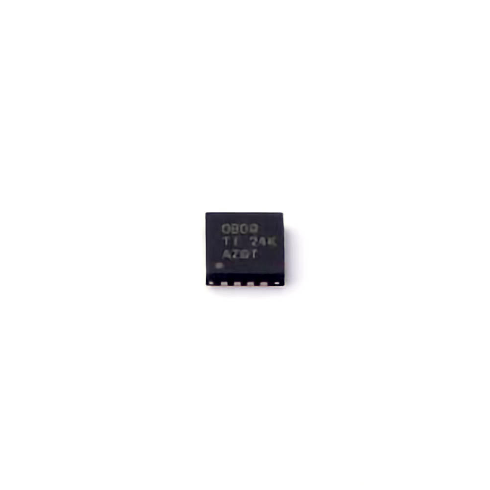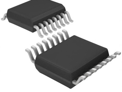
The TI OPA211AIDR is a precision operational amplifier that is often used in high-performance analog systems. While this component is known for its excellent specifications, users may still encounter issues during integration or use. This article explores common troubleshooting scenarios and provides practical solutions for the OPA211AIDR, enabling engineers to quickly resolve problems and optimize performance.
Common Troubleshooting Issues with OPA211AIDR
The OPA211AIDR, renowned for its low noise, high precision, and wide voltage range, is an ideal choice for various applications such as signal conditioning, instrumentation, and audio systems. Despite its advanced features and reliability, users may experience difficulties during integration or operation. Understanding these common issues and their causes is the first step in resolving them efficiently.
1.1 Power Supply Issues
One of the most frequent issues encountered with the OPA211AIDR is power supply-related problems. The OPA211AIDR requires a stable dual power supply for optimal performance, typically ranging from ±2V to ±18V. Power supply issues can cause instability, distortion, or even failure of the device.
Common Symptoms:
Unstable output voltage.
Inconsistent or fluctuating signal behavior.
Amplifier failure to power up or operate.
Potential Causes and Solutions:
Inadequate Voltage Levels: Ensure the supply voltage is within the recommended range. Too low or too high a voltage can lead to the amplifier's failure to operate correctly.
Power Supply Noise: Noise from the power supply can significantly affect the OPA211AIDR’s performance, leading to unwanted distortion. Consider adding filtering Capacitors near the power pins to minimize high-frequency noise.
Improper Grounding: Grounding issues can cause unexpected behavior in the amplifier. Make sure that the ground connections are properly made and are free from significant impedance, as this can directly impact signal integrity.
1.2 Incorrect Input Biasing
The OPA211AIDR requires proper input biasing to function optimally. Incorrect biasing can result in issues such as high offset voltages or distorted output.
Common Symptoms:
Amplified signals appear offset from the expected range.
The input signal seems distorted or unstable.
Potential Causes and Solutions:
Imbalanced Input Impedances: Ensure that the input Resistance s are balanced for both the inverting and non-inverting terminals. Imbalanced impedance can lead to inaccurate operation.
Improper Use of External Components: If you're using resistors or capacitor s to bias the inputs, ensure they are of the correct value and tolerance. Sometimes a mismatch can cause voltage drifts that negatively affect performance.
Excessive Input Voltage: The OPA211AIDR has input voltage limits, typically 40mV above or below the rails, depending on the power supply configuration. Ensure that the input signals stay within the specified limits.
1.3 Output Clipping
Output clipping is another common issue that can occur when using the OPA211AIDR. This issue is typically caused by the amplifier trying to drive a signal beyond its output swing limitations, often a result of improper feedback network design or excessive input voltage.
Common Symptoms:
Distorted or flat output signal.
Output voltage not tracking the input signal properly.
Potential Causes and Solutions:
Overdriving the Output: Ensure that the output signal remains within the OPA211AIDR's output swing limits, typically within the supply rails. If necessary, adjust the feedback network or reduce the input signal level.
Feedback Network Configuration: Incorrect feedback resistors or gain settings can cause the output to attempt to exceed the allowable range. Verify the feedback loop and ensure the gain is set appropriately.
Load Impedance Issues: If the load connected to the amplifier is too low in impedance, it may cause excessive current draw, leading to clipping. Ensure that the load impedance is within the amplifier's rated specifications.
1.4 Excessive Noise or Distortion
Although the OPA211AIDR is a precision low-noise operational amplifier, users might still experience noise or distortion in some cases, especially when used in sensitive applications. Identifying the root cause of this noise is crucial for restoring signal integrity.
Common Symptoms:
Unwanted high-frequency noise or hum in the output signal.
Distorted output even with low-noise input signals.
Potential Causes and Solutions:
External Interference: Noise from nearby components or electromagnetic interference ( EMI ) can affect the amplifier's performance. Use proper shielding and layout techniques to minimize interference. Consider placing the OPA211AIDR in a faraday cage or using EMI filters on input and output lines.
Improper Capacitor Selection: Inadequate or incorrectly chosen bypass capacitors on the power supply pins can introduce noise. Choose capacitors with low ESR (Equivalent Series Resistance) and place them as close as possible to the power pins of the amplifier.
PCB Layout Problems: Long, unshielded traces, poor grounding, or inadequate decoupling can lead to increased noise. Optimize the PCB layout by minimizing trace lengths, ensuring proper grounding, and using sufficient decoupling capacitors.
1.5 Thermal Issues
Thermal management is essential when working with precision amplifiers like the OPA211AIDR. Excessive heat can affect the performance of the device and lead to permanent damage.
Common Symptoms:
Sudden loss of functionality or degradation in performance.
Overheating of the amplifier or surrounding components.
Potential Causes and Solutions:
High Power Dissipation: If the OPA211AIDR is dissipating too much power, it may overheat. This is particularly true if operating close to the upper voltage limits. To mitigate this, ensure proper heat sinking and avoid pushing the amplifier to its maximum ratings.
Inadequate Ventilation: Ensure that the environment around the OPA211AIDR allows for proper airflow. Poor ventilation can cause the component to overheat, even under normal conditions.
Advanced Troubleshooting and Optimization Techniques for OPA211AIDR
While resolving basic issues is essential, advanced troubleshooting techniques can help optimize the performance of the OPA211AIDR in complex applications. These techniques focus on improving overall system performance, eliminating sources of error, and ensuring that the amplifier operates at its highest potential.
2.1 Fine-Tuning the Offset Voltage
The OPA211AIDR is known for its low input offset voltage, but in some applications, even small offsets can lead to significant errors. Properly managing offset voltage is critical in precision applications.
Common Symptoms:
Output voltage drifts even when the input is zero.
Small signal distortions over time.
Potential Causes and Solutions:
Trimming the Offset Voltage: If offset voltage is critical to the application, consider using external trimming circuits to fine-tune the offset. Many precision op-amps, including the OPA211AIDR, have offset nulling pins that allow users to correct small drifts manually.
Using External Capacitors: Adding a small capacitor (typically in the range of picofarads) between the offset nulling pins can improve long-term stability and reduce drift in some cases.
2.2 Ensuring Proper PCB Layout
Effective PCB layout is one of the most critical aspects of ensuring optimal performance in precision analog circuits. Poor PCB layout can lead to a variety of issues, including increased noise, signal degradation, and thermal problems.
Common Symptoms:
Increased noise levels.
Signal instability.
Potential Causes and Solutions:
Minimize Signal Path Lengths: Ensure that the signal paths are as short as possible to reduce the impact of noise and parasitic inductances. Keep high-frequency traces away from noisy components such as clocks or switching regulators.
Use Ground Planes: A solid ground plane provides a low-impedance return path for signals and helps to reduce noise. Use separate planes for analog and digital grounds, with a careful connection between them.
Decoupling Capacitors: Use multiple decoupling capacitors with varying values (e.g., 0.1µF and 10µF) to filter out noise across a wide frequency range. Place them as close to the OPA211AIDR as possible.
2.3 Temperature Compensation
Temperature-induced changes in the OPA211AIDR’s parameters, such as offset voltage or bias current, can introduce errors in sensitive applications. Understanding and compensating for these temperature effects can help improve system accuracy.
Common Symptoms:
Performance degradation as temperature changes.
Drifting or unstable readings in temperature-sensitive applications.
Potential Causes and Solutions:
Using a Reference Voltage: Employ a stable reference voltage that is less sensitive to temperature variations. This reference can be used to calibrate the amplifier's output under varying conditions.
Thermal Compensation Circuits: Implementing external temperature compensation circuits or using thermistors to adjust the system based on the temperature readings can minimize the impact of temperature variations.
2.4 Exploring Advanced Filtering Techniques
In applications requiring minimal noise or distortion, filtering is key to achieving optimal results with the OPA211AIDR. Advanced filtering techniques can significantly improve signal integrity.
Common Symptoms:
High-frequency noise or harmonic distortion.
Potential Causes and Solutions:
Low-Pass Filters: Use precision low-pass filters to remove high-frequency noise or unwanted harmonics before the signal enters the amplifier. Ensure that the filter’s cutoff frequency is below the amplifier’s bandwidth.
Active Filters: In some cases, active filters can be used in conjunction with the OPA211AIDR to further reduce noise. These filters use the amplifier itself in the filter circuit, offering better performance than passive filters alone.
By understanding common troubleshooting scenarios and employing advanced techniques to address these challenges, users can maximize the performance of the OPA211AIDR and ensure reliable operation in even the most demanding applications.
If you're looking for models of commonly used electronic components or more information about OPA211AIDR datasheets, compile all your procurement and CAD information in one place.
(Partnering with an electronic component supplier) sets your team up for success, ensuring that the design, production and procurement processes are streamlined and error-free. (Contact us) for free today


