Understanding the TPS7B6933QDCYRQ1 and Common Troubleshooting Issues
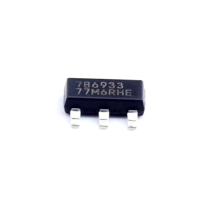
The TPS7B6933QDCYRQ1 is a state-of-the-art low-dropout (LDO) regulator manufactured by Texas Instruments, designed to provide a stable output voltage while maintaining high efficiency. With its ultra-low noise and high output current capabilities, it is ideal for Power ing sensitive analog and digital circuits. Despite its robust design, users may encounter some common troubleshooting challenges. Understanding these issues and knowing how to resolve them can save time and ensure the reliable pe RF ormance of your power systems.
1. Output Voltage Instability or Ripple
One of the most common issues users experience with the TPS7B6933QDCYRQ1 is output voltage instability or excessive ripple. This can be particularly problematic in high-precision applications where voltage consistency is critical, such as audio equipment or measurement devices.
Possible Causes:
Inadequate capacitor Selection: The TPS7B6933QDCYRQ1 requires specific input and output Capacitors to stabilize its operation. Using incorrect capacitor types or values can lead to instability.
PCB Layout Issues: Poor PCB layout design can contribute to noise or oscillations, especially when the regulator is placed near noisy components or power traces.
Load Transients: Sudden changes in load can cause the output voltage to momentarily dip or spike.
Solutions:
Use Recommended Capacitors: Ensure that the input and output capacitors are selected according to the datasheet recommendations. Typically, low ESR (equivalent series resistance) ceramic capacitors are recommended to minimize ripple and ensure stability.
Optimize PCB Layout: Ensure that the power traces are as short and wide as possible to reduce resistance and inductance. Place the output capacitor as close as possible to the output pin, and avoid routing noisy signals near the LDO regulator.
Decouple Load Changes: To mitigate the effects of load transients, include a bulk capacitor (e.g., 10µF or higher) on the output side to absorb transient spikes and help maintain steady output voltage.
2. Thermal Shutdown
Thermal shutdown is another common issue with the TPS7B6933QDCYRQ1, especially when the LDO regulator is handling high output currents or when there is insufficient heat dissipation.
Possible Causes:
Excessive Power Dissipation: The TPS7B6933QDCYRQ1 operates by dropping excess voltage as heat. If the difference between the input voltage and output voltage is large and the current is high, excessive heat may build up.
Inadequate Heat Sinking: If the regulator is mounted without adequate heat sinking or airflow, the internal temperature may rise above the specified threshold, triggering thermal shutdown.
Solutions:
Use a Proper Heat Sink: To prevent thermal shutdown, ensure that the TPS7B6933QDCYRQ1 is equipped with adequate heat dissipation mechanisms. Using a larger PCB area or incorporating a dedicated heat sink can significantly reduce the operating temperature.
Minimize Input-Output Voltage Difference: If possible, reduce the difference between the input and output voltage to decrease the power dissipation across the regulator.
Increase Airflow: In designs where the regulator is enclosed, consider adding ventilation or heat-dissipating elements to ensure sufficient airflow around the regulator.
3. Startup Failures or Delayed Start
Another issue that may arise is the failure of the TPS7B6933QDCYRQ1 to start up properly or a delayed start-up, which can impact the reliability of the system.
Possible Causes:
Insufficient Input Voltage: If the input voltage is below the minimum required for the regulator to operate (typically around 2.4V for the TPS7B6933QDCYRQ1), the LDO may not start up at all.
Power Supply Noise: Significant noise on the input power supply may prevent the regulator from achieving a stable startup.
Improper Enable Pin Configuration: If the enable (EN) pin is not configured properly, the regulator may fail to start or exhibit delays.
Solutions:
Check Input Voltage: Ensure that the input voltage meets or exceeds the minimum requirement for stable operation. Also, consider the transient characteristics of the power source to avoid startup failures caused by brief dips below the required voltage.
Reduce Input Noise: Use appropriate filtering (such as ferrite beads or decoupling capacitors) on the input supply to minimize noise and ensure clean power for the regulator.
Verify Enable Pin Logic: Confirm that the enable pin (EN) is properly tied to the correct logic level. If using an external enable signal, ensure it is driven to the required high or low state for proper startup.
Advanced Troubleshooting and Further Solutions
While the TPS7B6933QDCYRQ1 is generally reliable, understanding the more advanced troubleshooting techniques can be valuable when dealing with complex issues or specific application requirements. Below, we explore some additional common issues and their solutions to ensure the regulator operates optimally in all conditions.
4. Oscillations or Unwanted Noise
Some users may notice oscillations or unwanted noise in the output voltage, even with the recommended capacitors and proper layout.
Possible Causes:
Capacitor ESR Issues: A capacitor with too low or high an ESR value can cause instability in the regulator.
Inductive Components in Close Proximity: Inductors , transformers, or other inductive components located near the TPS7B6933QDCYRQ1 can cause oscillations or noise coupling into the regulator.
Improper Grounding: Insufficient or shared ground paths can cause noise to loop back into the regulator, leading to instability.
Solutions:
Optimize Capacitor Selection: Experiment with different capacitors to find the optimal ESR for stability. Typically, an ESR between 10mΩ and 200mΩ is recommended for stability in LDOs like the TPS7B6933QDCYRQ1.
Separate Ground Paths: To prevent noise from circulating, create dedicated ground paths for the regulator’s sensitive components and avoid shared ground planes for noisy components like switching regulators.
Shielding and Layout Tweaks: If oscillations persist, consider adding a shield around the LDO regulator or rerouting sensitive traces away from inductive sources.
5. Overvoltage Protection and Overcurrent Issues
In some applications, users may encounter issues where the TPS7B6933QDCYRQ1 is exposed to higher-than-expected voltages or currents, causing the device to shut down or enter protection mode.
Possible Causes:
Inrush Current: During power-up, inrush current can temporarily exceed the regulator’s current rating, triggering overcurrent protection.
Overvoltage on Input: If the input voltage exceeds the absolute maximum ratings of the TPS7B6933QDCYRQ1, the regulator may shut down or fail.
Incorrect Load Configuration: An excessive load on the output can cause the regulator to enter overcurrent protection mode.
Solutions:
Use Soft-Start Techniques: Incorporate soft-start circuitry or current-limiting components to reduce inrush current at startup.
Monitor Input Voltage: Use an overvoltage protection circuit to protect the regulator from transient spikes or sustained overvoltage conditions.
Check Load Rating: Ensure that the load connected to the regulator does not exceed its output current capacity. If necessary, use a current-limiting resistor or fuse.
6. Application-Specific Troubleshooting
Certain applications, such as RF or precision analog circuits, may present unique challenges with the TPS7B6933QDCYRQ1.
Possible Causes:
High-Frequency Noise Interference: In RF applications, the regulator’s output may be susceptible to high-frequency noise, impacting signal integrity.
Precision Error in Analog Applications: The low-dropout regulator’s output may not meet the stringent requirements for highly sensitive analog circuits in some cases.
Solutions:
Use Additional Filtering: In RF applications, consider using additional EMI filtering components like ferrite beads or low-pass filters on the output to suppress high-frequency noise.
Precision Testing: In precision analog applications, carefully test the output under various load and environmental conditions. Consider adding additional decoupling and filtering stages to meet stringent requirements.
By understanding and troubleshooting the common issues associated with the TPS7B6933QDCYRQ1, users can significantly enhance the performance and reliability of their designs. Whether you're dealing with instability, thermal shutdown, or startup delays, the above solutions provide practical and effective ways to address these challenges. By following best practices in capacitor selection, PCB layout, and component configuration, you can ensure that your application achieves optimal power management and performance.
If you're looking for models of commonly used electronic components or more information about TPS7B6933QDCYRQ1 datasheets, compile all your procurement and CAD information in one place.
( Partnering with an electronic component supplier) sets your team up for success, ensuring that the design, production and procurement processes are streamlined and error-free. (Contact us) for free today.


