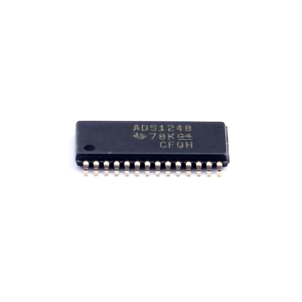
This article explores the application and debugging skills required to leverage the ADS1248IPWR , a high-precision Analog-to-Digital Converter (ADC), in Sensor interface s. By focusing on real-world applications and troubleshooting techniques, we highlight the significant role of this device in developing accurate, reliable sensor systems for industrial, medical, and other high-precision fields.
Introduction to ADS1248IPWR and its Application in High-Precision Sensor Interfaces
In the world of modern sensor systems, the accuracy of data conversion plays a critical role in ensuring the reliability and effectiveness of measurements. Whether you're designing a medical device that requires the precise measurement of vital signs or an industrial system monitoring environmental conditions, the need for high-precision Analog-to-Digital Converters (ADCs) is undeniable. Among the myriad of options available, the ADS1248IPWR stands out due to its remarkable capabilities in sensor interfaces.
The ADS1248IPWR is a high-precision, 24-bit ADC from Texas Instruments, specifically designed for applications requiring extremely accurate analog-to-digital conversion. With a low noise floor, high input impedance, and a range of configurable settings, the ADS1248IPWR is ideal for interfacing with sensors such as thermocouples, strain gauges, load cells, and other analog transducers.
This article dives into how the ADS1248IPWR is applied in high-precision sensor interfaces, followed by essential debugging techniques that are necessary for ensuring the optimal performance of such systems.
Why Choose the ADS1248IPWR?
The ADS1248IPWR excels in applications that demand both high precision and low Power consumption. Its 24-bit resolution and low noise characteristics make it an excellent choice for applications such as:
Load cells and strain gauges: These sensors require high accuracy for measuring minute changes in weight or pressure. The ADS1248IPWR’s high resolution makes it suitable for such delicate measurements.
Medical instrumentation: Devices such as electrocardiogram (ECG) or electroencephalogram (EEG) machines benefit from its ability to accurately convert small analog signals.
Industrial sensors: Systems monitoring temperature, pressure, or humidity can rely on the ADC’s accuracy to ensure precise control and monitoring.
Given its capabilities, the ADS1248IPWR has become the go-to ADC in industries requiring reliable, noise-resistant, and high-resolution analog-to-digital conversion.
Key Features of the ADS1248IPWR
Before diving into its applications, it’s essential to understand the core features of the ADS1248IPWR that make it stand out for sensor interfaces:
24-bit resolution: The ADS1248IPWR offers 24-bit resolution, which means it can convert the smallest changes in the input signal, providing ultra-high accuracy.
Programmable gain amplifier (PGA): The integrated PGA allows users to adjust the gain according to the sensor’s output range, maximizing the effective resolution of the ADC.
Low noise: Noise immunity is essential when dealing with small signals, and the ADS1248IPWR is designed with low noise characteristics to ensure signal integrity.
Configurable input channels: The ADS1248IPWR provides flexible channel configurations, allowing for differential and single-ended inputs to suit various sensor types.
On-chip temperature sensor: For temperature compensation in sensitive measurements, the integrated temperature sensor provides the ability to account for thermal variations.
These features make the ADS1248IPWR well-suited to a broad array of sensor applications where high accuracy and low noise are paramount.
Practical Applications of the ADS1248IPWR in Sensor Systems
1. Load Cells and Strain Gauges
Load cells and strain gauges are some of the most common sensors used in industrial and laboratory environments to measure force, pressure, or weight. These sensors output very small signals, often in the millivolt range, requiring a high-precision ADC to ensure the readings are accurate. The ADS1248IPWR, with its low noise and high resolution, is ideal for such applications. By using its integrated PGA, designers can amplify the signal and achieve even greater measurement accuracy.
2. Medical Devices
In medical devices like ECG or EEG machines, the accuracy of the measurements is of critical importance. The ADS1248IPWR can convert the analog signals from electrodes into high-precision digital data that can be analyzed for irregularities or abnormalities. Its ultra-low noise and high accuracy ensure that even subtle variations in the patient’s signals are detected, leading to better diagnosis and patient care.
3. Environmental Monitoring
For environmental monitoring, sensors such as temperature, humidity, and gas detectors require precise digital output to allow for real-time monitoring and control. Whether it’s monitoring industrial processes or outdoor conditions, the ADS1248IPWR offers the precision and flexibility necessary for such applications. The low noise level ensures that small variations in environmental factors are captured accurately.
4. Industrial Automation and Control
In the field of industrial automation, the ADS1248IPWR plays a crucial role in data acquisition for process control. Whether it’s for measuring pressure, flow, or other physical quantities, high-precision ADCs are necessary to ensure that the control systems react accurately and promptly. The ADS1248IPWR can interface with a wide range of industrial sensors, providing accurate digital signals for further processing and decision-making.
Debugging Techniques for Optimal Performance of ADS1248IPWR in Sensor Interfaces
Despite its high performance, working with the ADS1248IPWR in a sensor interface requires careful attention to detail. In practice, ADCs like the ADS1248IPWR are often a source of problems during system development, primarily due to issues like noise interference, grounding problems, or incorrect configuration settings. Debugging such issues requires a systematic approach and a deep understanding of both the ADC and the sensor systems.
1. Ensuring Proper Power Supply Decoupling
One of the most common sources of error in high-precision sensor systems is noise from the power supply. The ADS1248IPWR is particularly sensitive to power supply noise due to its high resolution and low noise characteristics. To minimize noise from the power source, it's essential to use proper decoupling capacitor s close to the ADC’s power pins.
Recommended Debugging Steps:
Use a low-pass filter (e.g., 100nF ceramic capacitors) to filter high-frequency noise.
Implement a separate analog and digital ground plane to prevent cross-talk between the digital and analog circuitry.
Verify the power supply voltage is stable and meets the ADC’s required range.
2. Signal Integrity and PCB Layout Considerations
The integrity of the input signal is paramount in achieving accurate conversions. Proper PCB layout can greatly reduce signal degradation due to parasitic capacitances, inductances, and unwanted noise.
Recommended Debugging Steps:
Keep analog signal traces as short as possible.
Use differential pair routing for signals to minimize noise susceptibility.
Use guard traces or shielding to protect sensitive signals from external noise.
3. Configuring the PGA (Programmable Gain Amplifier)
The ADS1248IPWR features a PGA that allows the amplification of small signals to maximize the ADC’s resolution. However, improper gain settings can lead to saturation or low signal resolution, resulting in inaccurate data conversion.
Recommended Debugging Steps:
Verify the sensor’s output range and choose an appropriate PGA setting.
Ensure that the input signal stays within the ADC’s full-scale input range to avoid clipping.
Consider testing with different gain settings to achieve the best balance between signal amplitude and noise performance.
4. Differential versus Single-Ended Input Mode
The ADS1248IPWR supports both differential and single-ended input modes. In high-precision applications, differential inputs often provide better performance, particularly when dealing with low-level signals and reducing common-mode noise. Choosing the correct input mode is crucial.
Recommended Debugging Steps:
If your sensor outputs a differential signal, ensure that the ADC is configured to operate in differential mode.
For single-ended sensors, ensure proper ground reference and consider differential input for better noise rejection.
5. Handling Temperature Effects
The ADS1248IPWR includes an internal temperature sensor to compensate for thermal drift, which is a common source of errors in high-precision applications. However, thermal effects on external components (like resistors in the sensor network) can still cause inaccuracies.
Recommended Debugging Steps:
Use the onboard temperature sensor to compensate for temperature-induced changes in sensor readings.
Implement additional temperature compensation algorithms if the sensor system is highly sensitive to thermal variations.
6. Noise Reduction Techniques
Noise is one of the most common issues that affect ADC performance, particularly in high-precision systems. External electromagnetic interference ( EMI ), power supply noise, and ground loops can all contribute to inaccuracies in the data conversion process.
Recommended Debugging Steps:
Use shielding around sensitive components to reduce EMI.
Implement proper grounding techniques to prevent ground loops and ensure a clean reference voltage.
Utilize filtering techniques to reduce high-frequency noise before the signal reaches the ADC.
Conclusion
The ADS1248IPWR is a powerful tool for high-precision sensor interfaces, but achieving optimal performance requires careful system design and attention to detail. Understanding its features, selecting the right configuration for the sensor being used, and applying effective debugging techniques will help engineers design reliable and accurate sensor systems. By mastering both application and debugging skills, designers can ensure that their systems deliver precise and trustworthy measurements in even the most demanding environments.
If you are looking for more information on commonly used Electronic Components Models or about Electronic Components Product Catalog datasheets, compile all purchasing and CAD information into one place.


