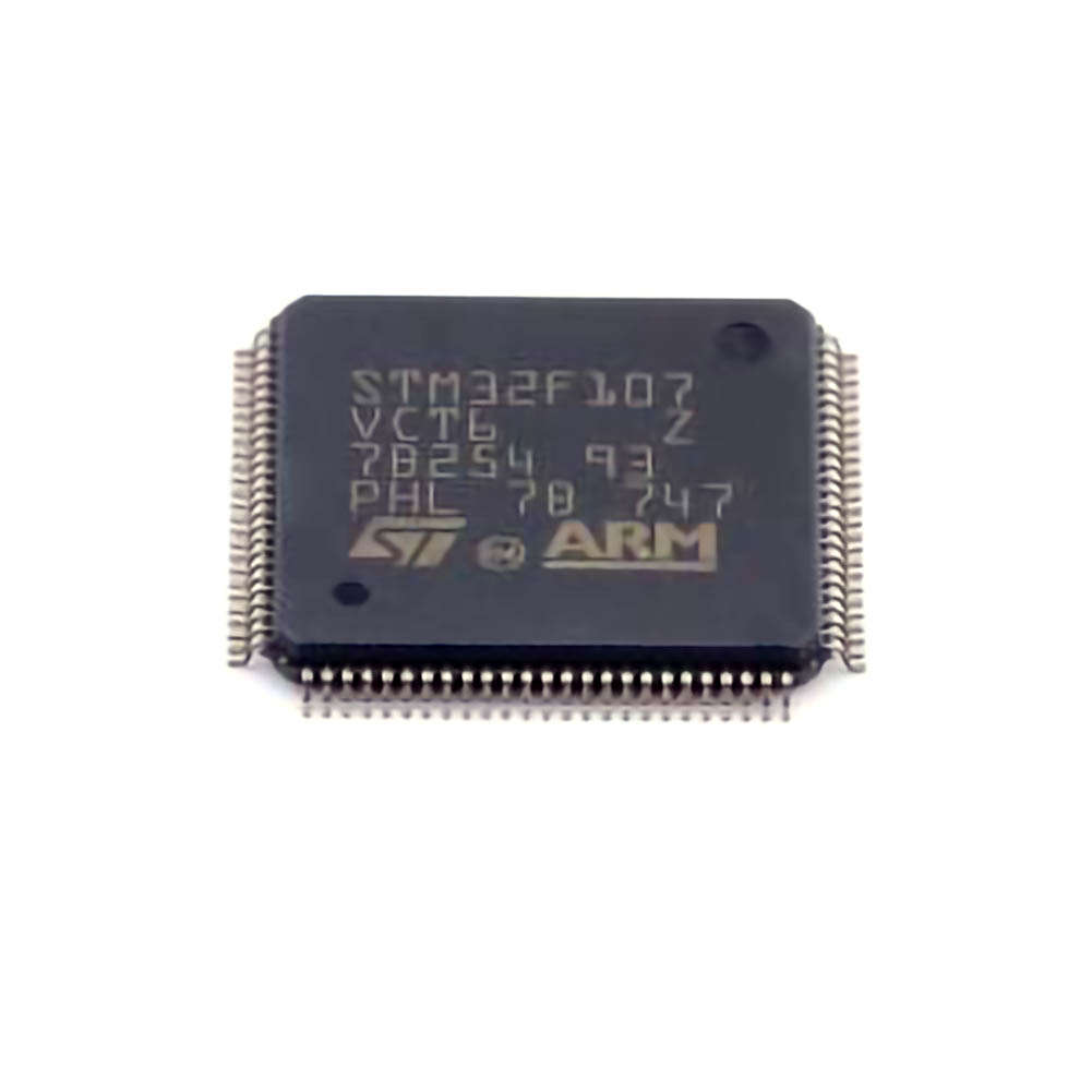
This STMicroelectronics article offers a comprehensive guide to common troubleshooting techniques for the STM32F107VCT6 microcontroller, focusing on solutions for Power issues, peripheral malfunctions, software problems, and more. Whether you're a beginner or an experienced developer, this article will help you efficiently identify and resolve problems related to the STM32F107VCT6, ensuring smooth operation in your embedded projects.
STM32F107VCT6, troubleshooting STM32, microcontroller issues, STM32F107VCT6 solutions, embedded system debugging, STM32 power issues, STM32 peripherals, software debugging, STM32F107VCT6 common errors, STM32F107 debugging
Identifying and Resolving Common STM32F107VCT6 Issues
The STM32F107VCT6 is a powerful microcontroller widely used in embedded systems for applications ranging from industrial control to consumer electronics. Despite its reliability and robust features, developers often encounter various issues when working with the STM32F107VCT6. This section will walk through common problems, focusing on troubleshooting techniques for power-related issues, peripheral configurations, and basic software problems.
Power Supply and Boot Problems
One of the most common issues with STM32 microcontrollers is related to the power supply. The STM32F107VCT6 is designed to operate with a supply voltage range from 2.0V to 3.6V. Ensuring that your system has a stable and clean power source is essential to prevent erratic behavior.
Symptoms:
Microcontroller does not power on.
Unreliable operation or crashes during runtime.
Booting issues.
Solutions:
Check Voltage Levels: Start by verifying that the supply voltage is within the acceptable range (2.0V to 3.6V). A multimeter or oscilloscope can help measure the actual voltage being delivered to the MCU pins. Fluctuations in power supply voltage can lead to unpredictable behavior.
Power Decoupling: Add appropriate decoupling Capacitors (e.g., 100nF ceramic capacitor s) close to the power pins (VDD and VSS) to stabilize the voltage. Capacitors help filter out noise and provide a local energy reservoir during transient events.
Power-on Reset Circuit: If the microcontroller fails to reset or boot up correctly, ensure that the power-on reset circuit is functioning as expected. For the STM32F107VCT6, the reset can be triggered by a power-on-reset IC or by using the internal reset circuitry. Verify that the reset pin (NRST) is correctly pulled low during power-up.
External Components: If your board includes additional components like voltage regulators, ensure that these parts are correctly rated and functioning. Faulty regulators or improperly connected components can cause power failures.
Debugging Peripherals and Communication interface s
STM32F107VCT6 is equipped with several peripherals such as GPIOs, UARTs , I2C, SPI, and timers. Misconfigurations of these peripherals often cause the most frustration during development. Let's examine some of the common peripheral issues and their solutions.
Symptoms:
Communication failures over UART, SPI, or I2C.
GPIO pins not responding to input or output commands.
Timers failing to generate interrupts or produce correct output.
Solutions:
GPIO Configuration Issues:
Incorrect Pin Mode: Ensure that you have correctly configured the GPIO pins for their intended function. GPIOs can be set to different modes like input, output, alternate function, or analog. Incorrect configuration can lead to malfunctioning peripherals. Use STM32CubeMX or direct register programming to verify pin settings.
Pin Remapping: On the STM32F107VCT6, certain alternate functions are assigned to specific pins. Check the datasheet and reference manual for correct pin mappings. Misconfigured alternate function settings can prevent peripherals from working correctly.
UART Communication Failures:
Baud Rate Mismatch: When using UART, mismatched baud rates between the microcontroller and external devices (such as a PC or GPS module ) can lead to corrupted data. Double-check the baud rate settings in both the MCU and the external device.
Framing Errors: Use STM32’s built-in error flags to identify framing errors, parity errors, and overrun errors. These flags can be Access ed via the USART_SR register and can help you troubleshoot communication issues.
DMA Buffering: For high-speed communication, consider using DMA (Direct Memory Access) to offload data transfers from the CPU, which improves performance. Ensure that the DMA channels are configured correctly and that buffer pointers are valid.
I2C/SPI Communication Problems:
Clock Speed: Make sure the SCL clock speed is within the specified range for I2C communication. Higher speeds can cause noise, and lower speeds might result in slower communication than necessary.
Pull-up Resistors : For I2C communication, ensure that proper pull-up resistors (typically 4.7kΩ) are used on the SDA and SCL lines. Without these, I2C communication will fail to function correctly.
Bus Arbitration: In SPI or I2C, check for bus contention or arbitration errors, especially if multiple devices are connected to the same bus. This is a common issue in complex systems with several peripherals.
Timer Configuration Issues:
Prescaler and Auto-Reload Register: Incorrectly setting the prescaler and auto-reload values in timer registers can cause the timer to overflow too soon or too late. Double-check your calculations for the desired timer frequency.
Interrupt Enablement: If using timers to generate interrupts, ensure the interrupt enable bit is set in the TIMx_DIER register. Additionally, confirm that the global interrupt enable bit is set in the NVIC to allow timer interrupt handling.
Debugging Software Issues
While hardware-related problems are often at the root of malfunctions, software bugs can also cause significant issues. Here are some common software-related problems and their troubleshooting solutions.
Symptoms:
Program crashes or unexpected behavior.
Hard faults or system resets.
The application doesn't execute as expected.
Solutions:
Check for Hard Faults:
Hard Fault Handler: The STM32F107VCT6 features a Hard Fault exception handler. When a critical fault occurs, the system enters this handler. You can use a debugger to inspect the program state when the hard fault occurs (e.g., stack pointer, program counter).
Fault Status Registers: The fault status registers (e.g., CFSR) contain information on the type of fault (e.g., memory management fault, bus fault). Investigate these registers to pinpoint the issue.
Stack Overflow:
Stack Pointer Analysis: If your application crashes with a Hard Fault or an unexpected reset, a stack overflow could be the cause. Ensure that the stack pointer is initialized properly, and check if your stack size is sufficient for the application. This is especially important in applications with deep function calls or large local variables.
Watchdog Timer (WDT) Issues:
WDT Configuration: If the application fails to run reliably, consider whether the independent watchdog (IWDG) or window watchdog (WWDG) is configured correctly. A misconfigured watchdog can cause an unwanted reset.
WDT Reset Prevention: Make sure that the watchdog timer is being properly serviced in the software. If the watchdog timer isn’t reset periodically, it will trigger a system reset, leading to unexpected reboots.
Software Debugging:
Debugging Tools: Utilize STM32CubeIDE, an excellent tool for debugging STM32 microcontrollers. It allows for real-time debugging, breakpoints, and variable tracking, which are invaluable for isolating software bugs. Alternatively, tools like OpenOCD or J-Link can provide low-level debugging capabilities.
Code Optimization: Check for common optimization pitfalls, such as infinite loops, memory leaks, or buffer overruns. These can lead to erratic behavior or system crashes.
Advanced Troubleshooting Techniques and Tips
In part two of this article, we will dive deeper into advanced troubleshooting techniques, including debugging complex systems, using advanced tools, and addressing intermittent issues that are common in embedded systems development. We will also explore some common misconceptions and offer practical tips for enhancing the reliability and efficiency of your STM32F107VCT6-based projects.
Advanced Debugging with Tools
Debugging embedded systems often involves a combination of hardware tools, software tools, and careful analysis. Below are some advanced techniques for effectively troubleshooting STM32F107VCT6-based systems.
Using JTAG/SWD for Advanced Debugging:
JTAG/SWD Interface: The STM32F107VCT6 supports both JTAG and Serial Wire Debug (SWD) for debugging. These interfaces provide access to the internal state of the MCU, allowing you to inspect registers, step through code, and set breakpoints.
Boundary Scan: With JTAG, you can use boundary scan features to detect issues with PCB connections, especially for complex systems with many peripherals. This can help detect issues that might not be immediately visible with traditional debugging.
Oscilloscope and Logic Analyzer:
Signal Integrity: If your microcontroller communicates with other devices via SPI, I2C, or UART, using an oscilloscope or logic analyzer can be invaluable. It helps verify signal integrity, check timing issues, and identify transmission problems that may not be visible in software alone.
Analyzing Waveforms: Oscilloscopes can capture voltage waveforms, allowing you to verify the timing of pulses, edges, and signal transitions, which is especially useful for peripherals like UART and I2C.
STM32CubeMX for Configuration Troubleshooting:
Peripheral Initialization: STM32CubeMX automatically generates initialization code for peripherals. It can be helpful in preventing common configuration mistakes. It also provides an interface to simulate peripheral configurations, ensuring the system behaves as expected before code deployment.
Handling Intermittent Issues
Intermittent issues can be some of the most difficult to debug in embedded systems. These issues often arise from power fluctuations, faulty components, or software timing bugs. Here are a few strategies to address these problems.
Systematic Stress Testing:
Temperature Variation: Some issues may only manifest under certain environmental conditions, such as temperature changes. Perform stress testing under varying environmental conditions (temperature, voltage levels, etc.) to identify potential root causes.
Checking External Components:
Peripheral Failures: Sometimes external components like sensors, power regulators, or communication modules can malfunction intermittently. Swap out components one at a time to isolate the faulty part of the system.
Firmware Updates and Patches:
Vendor Updates: Keep an eye on firmware updates from STMicroelectronics. Sometimes issues are caused by bugs in the MCU firmware or peripheral drivers, and a patch or updated driver might resolve the issue.
Conclusion
The STM32F107VCT6 is a robust and versatile microcontroller suitable for a wide range of embedded applications. However, as with any complex electronic system, developers may encounter a variety of issues related to power supply, peripheral configuration, and software bugs. By employing systematic troubleshooting methods, using advanced debugging tools, and keeping your development environment updated, you can efficiently diagnose and resolve common issues, ensuring reliable performance for your STM32-based projects.
If you are looking for more information on commonly used Electronic Components Models or about Electronic Components Product Catalog datasheets, compile all purchasing and CAD information into one place.


