part 1:
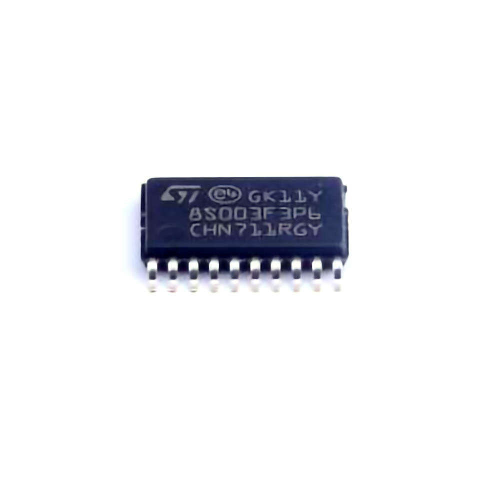
Introduction to the STM8S003F3P6 Microcontroller
The ST STM8S003F3P6 is a popular microcontroller in the STM8 family, designed by STMicroelectronics for embedded systems. With a 32-bit CPU, 8 KB of Flash Memory , and 1 KB of RAM, it offers a robust platform for a variety of applications, from simple devices to more complex electronic systems. However, as with any embedded system, users might run into several common issues when working with this microcontroller. Understanding these issues and learning how to troubleshoot them effectively can make a significant difference in project development and time efficiency.
1. Power Supply Issues
One of the first troubleshooting steps when dealing with the STM8S003F3P6 is to ensure that the power supply is stable and meets the microcontroller's requirements. The STM8S003F3P6 operates at a supply voltage between 2.95 V and 5.5 V, so deviations outside this range can cause malfunctions or prevent the microcontroller from functioning altogether.
Common Solutions:
Check the Voltage Regulator: Verify that the voltage regulator provides a steady voltage within the specified range.
Monitor Power Connections: Ensure that power and ground connections are secure and not prone to loose connections or soldering issues.
Measure Supply Voltage: Use an oscilloscope to check for voltage fluctuations that could indicate issues with the power supply.
2. Reset Circuit Problems
The reset circuit is crucial for initializing the STM8S003F3P6 properly. If the reset pin (NRST) is not working as expected, the microcontroller may not enter or exit reset mode correctly, leading to erratic behavior or failure to start.
Common Solutions:
Check NRST Pin Connection: Ensure that the reset pin is connected correctly to the circuit and is not influenced by noise or interference.
Add a capacitor : A small capacitor (e.g., 100nF) between the NRST pin and ground can help filter out noise and improve reset reliability.
Debounce the Reset Button: When using a manual reset button, consider adding a pull-up resistor and debounce circuitry to eliminate false triggers.
3. Communication Protocols and Peripheral Issues
Many applications for the STM8S003F3P6 involve communication protocols such as UART, SPI, and I2C. Problems in communication can cause data transfer failures and affect system functionality.
Common Solutions:
Check Pin Configurations: Verify that the pins used for communication are correctly configured as input/output and are set to the appropriate alternate function.
Debug with a Logic Analyzer: A logic analyzer can be invaluable for visualizing signals and diagnosing communication errors.
Ensure Proper Pull-up/Pull-down Resistors : For protocols like I2C, pull-up resistors on data and Clock lines are essential for proper operation.
Clock Configuration: Confirm that the clock system is configured correctly. Incorrect clock settings can lead to synchronization issues.
4. Flash Memory Programming and Verification
Programming the STM8S003F3P6 involves loading firmware into its Flash memory, which can sometimes result in problems if not done properly. Common issues include programming failures, corrupted code, or code that doesn’t execute as expected.
Common Solutions:
Use ST’s Programming Tools: Utilize the official ST-Link utility or the STM8S Discovery kit to reprogram the microcontroller and verify the code’s integrity.
Check for Write Protection: Ensure that the write protection bits in the Flash memory are correctly set or unset according to your application needs.
Verify the Code: After programming, use the debugger to step through the code and identify any areas that might be causing issues.
5. Debugging Tips and Tools
When troubleshooting an STM8S003F3P6, having the right debugging tools and methodologies can make a significant difference. A few valuable practices include:
Common Solutions:
Use an In-Circuit Debugger: A debugger, such as the ST-Link V2, is essential for setting breakpoints, stepping through code, and examining variables in real time.
Serial Output Debugging: For basic debugging, using UART or USB for serial output can help track program flow and variable states.
Simple LED Indicators: Employing an LED for basic feedback (e.g., toggling on certain conditions) can provide a straightforward method to check the state of specific code sections.
part 2:
6. Clock Configuration and Watchdog Timer Issues
The STM8S003F3P6 includes an internal clock system that may be subject to misconfiguration or issues that could cause system instability. Similarly, the Watchdog Timer (WDT) is a crucial safety feature that resets the microcontroller if it enters an unintended state.
Common Solutions:
Verify Clock Source: Double-check that the correct clock source (internal or external) is selected and properly configured in the microcontroller's control registers.
Check for WDT Timeout: If your microcontroller resets unexpectedly, ensure that the Watchdog Timer is being properly refreshed within the expected time frame.
Use a Stable Crystal Oscillator: If you’re using an external oscillator, confirm that the crystal is compatible with the STM8S003F3P6 specifications.
7. Pin and Port Configurations
Improper configuration of the microcontroller’s I/O pins can lead to errors, including the microcontroller not reading signals correctly or not outputting the desired state. Ensuring that the pin configurations are correct for the intended use is essential.
Common Solutions:
Pin Multiplexing: Make sure the correct alternate functions for pins are selected in the microcontroller’s register settings.
Input/Output Modes: Ensure that input pins are configured as inputs and output pins as outputs, with proper pull-up or pull-down resistors as necessary.
Avoid Floating Pins: Unused I/O pins should be configured as outputs or connected to a known state to prevent them from floating and causing erratic behavior.
8. Debugging External Components
External components connected to the STM8S003F3P6, such as sensors, actuators, and other peripherals, can contribute to issues if not properly interface d.
Common Solutions:
Check Component Voltage Levels: Ensure that external components operate at compatible voltage levels with the microcontroller’s I/O pins.
Examine Signal Integrity: Use an oscilloscope to verify that the signals sent and received by external components are clean and without noise.
Review Timing Requirements: Make sure that the timing specifications of the external components are compatible with the microcontroller’s capabilities.
9. Thermal Management
Although the STM8S003F3P6 does not generate significant heat under typical usage, high ambient temperatures or excessive current draw can lead to thermal issues that affect its performance.
Common Solutions:
Use Heatsinks or Cooling Solutions: For high-current applications or environments with high ambient temperatures, use heatsinks or passive cooling methods to maintain a stable operating temperature.
Monitor Temperature: Use a temperature sensor in critical applications to keep track of the microcontroller’s operating temperature.
10. Common Mistakes and How to Avoid Them
To wrap up, it's important to be aware of some common mistakes and how to avoid them:
Common Solutions:
Skipping the Datasheet Review: Always read the datasheet thoroughly before starting development to understand limitations and pin functions.
Overlooking Error Flags: Pay attention to error flags in communication protocols, as these can indicate issues that need to be resolved.
Rushing Debugging: Take your time when debugging. Hasty decisions and rapid changes can lead to overlooking important clues.
Conclusion
Working with the STM8S003F3P6 microcontroller can be a rewarding experience when you have a good understanding of common troubleshooting techniques. By following the solutions outlined in this article, you’ll be better equipped to diagnose and resolve issues efficiently, ensuring that your projects run smoothly and reliably.
If you're looking for models of commonly used electronic components or more information about STM8S003F3P6 datasheets, compile all your procurement and CAD information in one place.
(Partnering with an electronic component supplier) sets your team up for success, ensuring that the design, production and procurement processes are streamlined and error-free. (Contact us) for free today


