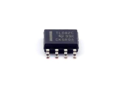
The TL074IDR is a popular operational amplifier (Op-Amp) known for its high performance in various applications, from audio equipment to signal processing systems. However, like any electronic component, it is susceptible to noise issues that can degrade system performance. This article explores common noise problems associated with the TL074IDR Op-Amp and offers practical solutions to diagnose and solve them, ensuring clean and reliable operation.
Identifying and Diagnosing Noise Issues with TL074IDR Op-Amp
The TL074IDR Op-Amp is renowned for its versatility, often employed in signal conditioning, active filters , and audio Amplifiers . However, despite its high quality, users sometimes encounter unwanted noise. Noise in Op-Amp circuits can manifest as hum, static, or random fluctuations, and it can be particularly detrimental in precision applications such as audio processing and instrumentation. In this section, we’ll explore the common causes of noise and methods for diagnosing these issues.
1.1 Understanding Noise in Operational Amplifiers
Before diving into diagnosis and solutions, it’s crucial to understand the types of noise that can affect an operational amplifier like the TL074IDR. The primary sources of noise in Op-Amp circuits can be categorized as:
Thermal Noise: Generated by the random motion of electrons in Resistors and s EMI conductors, thermal noise is present in every electronic circuit. It is often higher in resistive elements and becomes more noticeable at higher frequencies.
Flicker Noise (1/f Noise): This low-frequency noise is more prominent at lower frequencies and can be especially problematic in audio or precision instrumentation applications.
Shot Noise: Arising from the discrete nature of charge carriers (electrons) moving through a conductor, shot noise is typically associated with diodes or transistor s but can also affect Op-Amp circuits, particularly in high-impedance configurations.
Power Supply Noise: Any irregularities in the power supply, such as voltage fluctuations or ripple, can cause noise in the Op-Amp’s output. Poor decoupling or noisy power rails are common culprits.
1.2 Checking for Circuit Design Issues
Noise issues in Op-Amp circuits often stem from the design itself. The TL074IDR, like other Op-Amps, requires a careful balance of component values, grounding, and layout to minimize noise interference. Below are common design-related sources of noise:
Impedance Mismatch: High input impedance configurations, such as those used in instrumentation amplifiers, can pick up more noise due to their sensitivity to external sources. Additionally, improper matching of the impedance between the Op-Amp and surrounding components can exacerbate noise problems.
Poor Grounding: Grounding issues are a leading cause of noise in Op-Amp circuits. A noisy or poorly implemented ground plane can introduce hum or random noise into the circuit. It’s essential to have a dedicated, low- Resistance ground path that minimizes noise interference.
PCB Layout: The physical layout of the printed circuit board (PCB) plays a vital role in minimizing noise. Long trace lengths, inadequate shielding, or improper placement of sensitive components can create unwanted coupling between signals and power lines, which increases noise levels.
1.3 Diagnosing Noise Using Oscilloscopes and Other Tools
When noise appears in a TL074IDR-based circuit, an oscilloscope is an invaluable tool for diagnosis. Here’s how you can use an oscilloscope to identify and analyze noise:
Visual Inspection of Output Signal: The first step is to look at the output signal using an oscilloscope. In a noise-free circuit, the waveform should resemble the expected signal—be it a sine wave, square wave, or other expected shapes. Noise will manifest as spurious signals, often appearing as jagged or irregular patterns overlaid on the primary waveform.
Frequency Spectrum Analysis: If the noise appears to be consistent and periodic, use a spectrum analyzer or a Fourier transform function in the oscilloscope to examine the frequency components of the signal. Flicker noise, for instance, will manifest as a low-frequency hum, while high-frequency noise could indicate issues with power supply decoupling or improper PCB layout.
Differential Diagnosis: By analyzing the signal at various points in the circuit (input, output, and power rails), you can pinpoint the origin of the noise. If noise is only present on the output but not at the input, the problem may lie within the Op-Amp itself or downstream circuitry.
1.4 Evaluating Power Supply and Decoupling
The TL074IDR, like all Op-Amps, is highly sensitive to the quality of the power supply. Noise in the power supply can easily couple into the Op-Amp, resulting in unwanted output noise. Power supply noise often manifests as high-frequency spikes or ripple. Common culprits include:
Power Supply Ripple: Ripple is the periodic fluctuation in the DC voltage provided by the power supply, often caused by inadequate filtering in the power conversion stage. This can directly influence the performance of the Op-Amp.
Improper Decoupling: Decoupling Capacitors are essential for filtering out high-frequency noise from the power supply. If these capacitor s are missing or incorrectly sized, power supply noise can couple into the Op-Amp, causing distortion or instability.
To diagnose power supply issues, check for ripple or fluctuations on the power rails using an oscilloscope. If ripple is present, adding or replacing decoupling capacitors near the Op-Amp’s power pins can often resolve the issue.
1.5 Environmental and External Noise Factors
Sometimes, the noise in a TL074IDR Op-Amp circuit may not be a result of design flaws or component failure but rather external interference. Factors such as electromagnetic interference (EMI) from nearby electrical equipment, radio-frequency interference (RFI), or even thermal fluctuations can contribute to unwanted noise. Here’s how to address external noise:
Shielding: If external interference is a problem, adding shielding around the circuit or using twisted-pair wires for sensitive signal lines can reduce EMI and RFI.
Physical Layout Changes: Moving the Op-Amp and its associated components away from sources of interference (e.g., motors, transformers, or high-voltage lines) can help minimize noise pickup.
Practical Solutions to Eliminate Noise in TL074IDR Circuits
In the first part of this article, we explored various ways to diagnose noise issues in TL074IDR-based circuits. In this section, we will focus on practical solutions to reduce and eliminate noise, ensuring the Op-Amp operates smoothly in its intended application.
2.1 Improving PCB Layout for Noise Minimization
An efficient and noise-free circuit design begins with the PCB layout. Proper layout techniques are critical for reducing noise in Op-Amp circuits. Consider the following recommendations:
Minimize Trace Lengths: Long signal paths can act as antenna s, picking up noise. Minimize trace lengths for critical signals, especially those carrying sensitive information, to reduce noise susceptibility.
Use Ground Planes: A solid, uninterrupted ground plane on the PCB can significantly reduce noise. Grounding traces should be kept wide and low-resistance to prevent noise from traveling through the ground network.
Shielding Sensitive Components: If your circuit is exposed to external sources of EMI, consider adding shielding around the Op-Amp or sensitive components to isolate them from noise sources.
Separate Analog and Digital Grounds: If your circuit involves both analog and digital signals, keep the analog and digital grounds separate and connect them at a single point (star grounding). This prevents digital noise from coupling into the analog circuitry.
2.2 Using Proper Decoupling Capacitors
To address power supply noise, proper decoupling of the Op-Amp is essential. Decoupling capacitors filter out high-frequency noise and provide a stable voltage to the Op-Amp. Here are best practices for decoupling:
Place Capacitors Close to Power Pins: Place a ceramic capacitor (typically 0.1µF) as close to the power supply pins of the TL074IDR as possible. This will effectively filter out high-frequency noise.
Use a Bulk Capacitor: In addition to small ceramic capacitors, use a bulk electrolytic capacitor (e.g., 10µF to 100µF) to stabilize the power supply and reduce low-frequency noise.
Choose Capacitor Values Wisely: The value of the decoupling capacitors should match the frequency characteristics of the noise. For high-frequency noise, a smaller value (e.g., 0.01µF) ceramic capacitor works best, while bulk capacitors help with lower-frequency fluctuations.
2.3 Thermal and Environmental Control
Excessive heat or unstable environmental conditions can exacerbate noise issues in Op-Amps. Ensure that the TL074IDR is operating within its specified temperature range. High temperatures can lead to increased noise and reduced performance. Consider the following strategies:
Thermal Management : If the Op-Amp is dissipating significant heat, improve cooling by using heat sinks or increasing airflow around the component.
Stable Environment: Avoid placing the circuit near sources of excessive heat or humidity. Ensure that the circuit operates within an environment with stable temperature and minimal vibrations, which can induce noise.
2.4 Choosing the Right External Components
Selecting the right external components, such as resistors and capacitors, is vital to minimize noise. Here are a few guidelines:
Low-Noise Resistors: When designing circuits that require low-noise operation, use metal-film resistors instead of carbon-film resistors. Metal-film resistors tend to have lower noise characteristics.
High-Quality Capacitors: Use high-quality, low-ESR (Equivalent Series Resistance) capacitors for decoupling and filtering applications. Electrolytic capacitors should be avoided in high-frequency applications.
2.5 Troubleshooting and Adjustments
If noise persists despite following best practices, consider these additional troubleshooting steps:
Check for Loose Connections: Loose or faulty connections can introduce noise, especially in high-impedance circuits. Ensure that all connections are secure.
Test with a Different Op-Amp: In some cases, a faulty TL074IDR Op-Amp might be the source of the noise. Testing with a different unit can help confirm whether the Op-Amp is the problem.
Optimize Input Signal: If the input signal is noisy, use additional filtering or signal conditioning before feeding it into the Op-Amp.
By following these diagnosis and solution strategies, you can effectively reduce and eliminate noise in TL074IDR Op-Amp circuits. Whether you are working with audio systems, precision instrumentation, or any other application requiring high-quality signal processing, addressing noise will ensure your designs perform optimally and reliably.
If you are looking for more information on commonly used Electronic Components Models or about Electronic Components Product Catalog datasheets, compile all purchasing and CAD information into one place.


