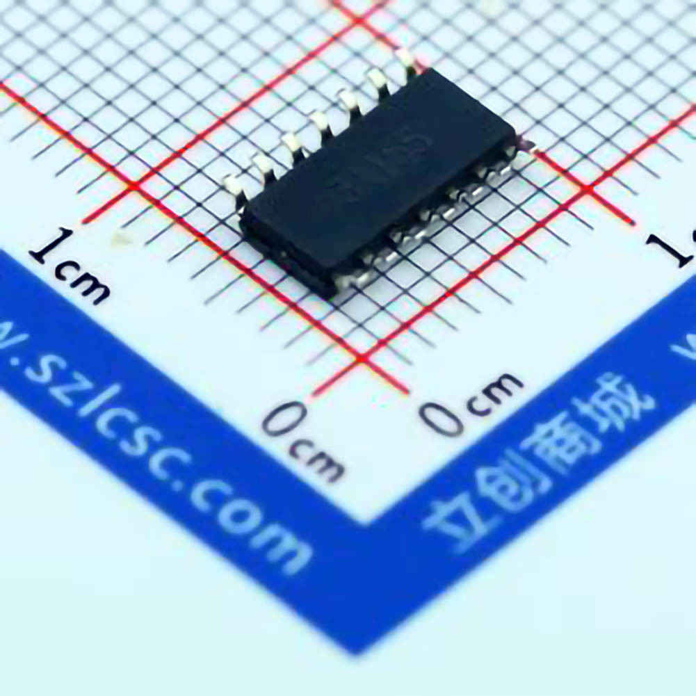
Understanding the TL084CDR and Common Noise Sources
The TL084CDR operational amplifier (op-amp) is a widely used component in both analog and digital circuit designs, praised for its low-noise characteristics and versatility in signal processing. However, like all electronic components, it is not immune to performance issues, particularly when it comes to noise.
In this first part of our guide, we will explore the TL084CDR in detail, identify potential sources of noise, and understand the specific circumstances under which noise becomes a problem.
What is the TL084CDR?
The TL084CDR is an op-amp designed for low-noise audio and general-purpose applications. It boasts features like low input bias current, high gain, and wide frequency response, making it ideal for a wide variety of applications, from signal amplification to audio processing.
One of its key selling points is its relatively low noise figure, which makes it a popular choice for high-fidelity audio equipment, measurement instruments, and other precision electronics. Despite these advantages, noise issues can still arise under certain conditions. Understanding why and how this happens is crucial for ensuring the TL084CDR performs optimally.
Common Sources of Noise in Amplifier Circuits
When noise problems occur in a circuit using the TL084CDR, it’s important to understand the common sources of noise that can affect the performance of an op-amp:
Thermal Noise (Johnson-Nyquist Noise):
All electronic components, including Resistors and transistor s, generate thermal noise due to the random motion of charge carriers within the component. The TL084CDR, being a s EMI conductor device, is no exception. Thermal noise typically becomes more prominent in high-resistance elements and can manifest as unwanted fluctuations in the output signal.
Shot Noise:
Shot noise arises from the discrete nature of electrical charge carriers (electrons) moving through semiconductor devices. In the context of an op-amp like the TL084CDR, shot noise can appear when the input transistors of the op-amp handle very small current flows, which is often the case when dealing with high-impedance sources.
Flicker Noise (1/f Noise):
Flicker noise, or low-frequency noise, is more noticeable at lower frequencies, such as those used in audio applications. It’s associated with imperfections in the semiconductor materials used to build the op-amp and typically manifests as a hum or low-frequency oscillation. In audio applications, flicker noise can significantly degrade the signal quality if not properly managed.
Power Supply Noise:
Noise introduced by the power supply is another common issue. If the op-amp’s supply voltage is not well-regulated or if the supply is contaminated with noise, the op-amp can pick up this interference, leading to additional noise at the output. This is especially problematic in sensitive audio circuits where a clean power source is crucial for maintaining signal integrity.
Electromagnetic Interference (EMI) and Crosstalk:
Electromagnetic interference from nearby circuits or devices can also affect the TL084CDR. Poor grounding, inadequate shielding, and improper layout design are common culprits in allowing EMI to influence the op-amp’s performance.
Feedback Loop Instability:
Noise problems in op-amps can sometimes be traced back to instability in the feedback loop. When feedback is not properly managed—either due to inappropriate component values or layout issues—oscillations or unintended behavior can introduce noise into the system.
Identifying Noise in TL084CDR Circuits
If you're encountering noise in a circuit with the TL084CDR, the first step is to clearly identify the source of the noise. The noise may manifest in several forms, including hum, buzz, hiss, or random fluctuations, and can affect the clarity and quality of the amplified signal.
Here are some steps to identify the noise:
Measure the Output:
Using an oscilloscope, measure the output of the op-amp while ensuring all other components (like resistors, capacitor s, and external circuitry) are functioning correctly. This will help you determine whether the noise is coming from the op-amp itself or from external sources.
Isolate the Problem:
One of the most effective troubleshooting techniques is to isolate different sections of the circuit. For example, disconnect the power supply, remove feedback components, or disconnect the signal input. This can help you pinpoint whether the noise is caused by the TL084CDR or another part of the circuit.
Check the Power Supply:
Power supply issues are often overlooked but can be the root cause of many noise problems. Use a multimeter or oscilloscope to check for fluctuations or noise on the power rails of the TL084CDR. If there’s noticeable ripple or instability, this may be the source of your issues.
Look for Ground Loops:
Ground loops can create a significant amount of noise, particularly in audio circuits. Make sure the circuit is grounded properly, and consider using star grounding or separate ground planes for sensitive parts of the circuit.
Assess the Circuit Layout:
Inadequate PCB layout or poor routing can exacerbate noise issues. Ensure that sensitive signal paths are kept away from noisy components and that traces are as short and direct as possible. Proper decoupling Capacitors placed close to the op-amp’s power pins can also help reduce power supply noise.
Summary of Part 1
In this section, we introduced the TL084CDR and discussed its low-noise characteristics, as well as the common sources of noise that could potentially affect its performance. We highlighted thermal noise, shot noise, flicker noise, power supply noise, electromagnetic interference, and feedback loop instability as the most common culprits. Identifying the specific source of the noise is critical before moving on to the next steps in resolving the issue.
In part two, we will go through the step-by-step process of resolving noise problems in TL084CDR-based circuits, providing actionable solutions for each identified cause.
Step-by-Step Guide to Resolving Noise Problems in TL084CDR Circuits
Now that we have a clear understanding of the potential sources of noise in TL084CDR circuits, we can begin to address and mitigate these issues. In this section, we will provide practical, step-by-step solutions for each of the noise sources identified in Part 1. Whether you’re working on audio amplifiers or any other sensitive signal processing application, these solutions will help you ensure that your TL084CDR delivers clean, accurate signals.
Step 1: Mitigating Thermal and Shot Noise
Thermal and shot noise are intrinsic to semiconductor devices like the TL084CDR, but their impact can be minimized with proper design practices.
Use Low-Noise Resistors:
The resistors used in your circuit play a crucial role in the level of thermal noise. For sensitive applications, choose low-noise, metal-film resistors with tight tolerances. These types of resistors have less thermal noise compared to carbon-film resistors.
Lower Impedance:
Noise generated by the TL084CDR tends to increase with higher source impedances. To reduce noise, try to lower the impedance of the input signal source or use a buffer stage with a low-impedance output. This will reduce the impact of thermal and shot noise on the signal.
Minimize Input Bias Current:
Ensure that the op-amp’s input bias current is not too high, as this can exacerbate shot noise. For the TL084CDR, the bias current is typically very low, but the circuit design should still take this into account, especially in high-impedance circuits.
Step 2: Reducing Flicker Noise (1/f Noise)
Flicker noise is particularly troublesome in audio circuits. Here are some strategies to minimize its impact:
Increase the Operating Frequency:
Flicker noise tends to dominate at low frequencies. If your application allows, increase the operating frequency of the circuit to move the noise outside the range of interest.
Use a High-Quality Power Supply:
A well-regulated power supply can significantly reduce the impact of flicker noise. Consider using a low-noise, regulated DC power supply with proper filtering to minimize any fluctuations that might cause noise.
Low-Pass Filtering:
Adding a low-pass filter to your design can help attenuate the low-frequency components of flicker noise, leaving the higher-frequency signal intact. Use capacitors with appropriate values to filter out the unwanted low-frequency noise.
Step 3: Dealing with Power Supply Noise
Power supply noise is one of the most common causes of unwanted noise in amplifier circuits. To address this, consider the following solutions:
Use Decoupling Capacitors:
Place decoupling capacitors as close as possible to the op-amp’s power pins (V+ and V-). A combination of small ceramic capacitors (e.g., 0.1 µF) and larger electrolytic capacitors (e.g., 10 µF) can effectively filter high-frequency noise from the power supply.
Improve Power Supply Filtering:
If your power supply is not sufficiently filtered, consider adding additional components such as inductors or ferrite beads to reduce ripple and high-frequency noise.
Separate Analog and Digital Grounds:
In mixed-signal systems, keep the analog and digital grounds separate to avoid digital noise coupling into the sensitive analog signal paths.
Step 4: Shielding and Layout Optimization for EMI
Electromagnetic interference (EMI) is another significant source of noise in circuits using the TL084CDR. Here’s how to minimize its impact:
Use Shielding:
If the circuit is susceptible to EMI, consider using metal enclosures or shielding to block external interference. Shielding can help protect the op-amp and other sensitive components from external noise sources.
Proper PCB Layout:
Carefully plan your PCB layout to minimize the loop area between power and ground traces, as large loops can act as antenna s and pick up external EMI. Keep high-speed digital traces away from sensitive analog traces.
Use Ground Planes:
Implementing a solid ground plane can reduce the risk of EMI and ensure that any noise is quickly dissipated, leading to cleaner operation of your TL084CDR circuit.
Step 5: Addressing Feedback Loop Instability
Finally, feedback loop instability can lead to noise problems, especially in high-gain circuits.
Adjust Feedback Network:
Review the values of resistors and capacitors in the feedback network. If the circuit oscillates or introduces noise, adjusting the feedback components or adding small compensation capacitors may help stabilize the loop.
Reduce the Gain:
In some cases, reducing the overall gain of the circuit can help minimize noise. Excessive gain can amplify not only the desired signal but also unwanted noise.
Conclusion
Resolving noise problems in TL084CDR-based circuits requires a systematic approach, addressing everything from component choice to layout optimization. By understanding the underlying causes of noise and applying the appropriate mitigation strategies, you can ensure that your TL084CDR operates with the clarity and precision that its design promises. Whether you're building high-fidelity audio systems or precision instrumentation, these steps will help you achieve clean, noise-free performance.
If you are looking for more information on commonly used Electronic Components Models or about Electronic Components Product Catalog datasheets, compile all purchasing and CAD information into one place.


