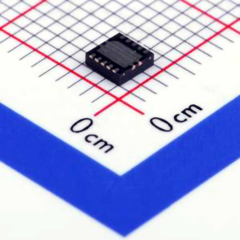
The Texas Instruments TPS51200DRCR is a popular Power management IC used in a wide range of applications. However, like any piece of technology, it can sometimes present issues that require troubleshooting. This article provides a detailed guide to understanding the most common problems users might face with the TPS51200DRCR and how to address them effectively.
TPS51200DRCR, troubleshooting, power management IC,common issues, voltage regulation, power supply, design optimization, power management, IC failure, PCB issues, load regulation.
Understanding the TPS51200DRCR and Common Troubleshooting Scenarios
The TPS51200DRCR is a power management IC (PMIC) that has gained significant popularity in a variety of electronic devices, particularly in those requiring precise voltage regulation and efficient power conversion. Whether it’s a laptop, industrial equipment, or embedded system, the TPS51200DRCR offers a reliable and highly integrated solution. However, just like any other electronic component, it’s not immune to issues. Understanding how to troubleshoot problems effectively is critical to ensuring your design runs smoothly and efficiently.
1.1. Key Features of the TPS51200DRCR
Before delving into the troubleshooting aspect, it is essential to have a clear understanding of the key features and functions of the TPS51200DRCR. This knowledge will help in identifying the root causes of issues and resolving them quickly.
The TPS51200DRCR is designed to provide high efficiency in step-down voltage conversion, and it can support output voltages from 0.6V to 5.5V. It’s particularly useful in applications that require efficient power management for processors, FPGA s, and memory systems. The IC offers features such as:
Low Dropout Voltage: Ensures efficient power conversion with minimal loss.
Flexible Output Voltage Range: Suitable for a wide variety of applications.
High Efficiency: Reduces heat and power consumption.
Multiple Protection Features: Including overcurrent, overvoltage, and thermal shutdown protections.
Adjustable Output Voltage: The voltage can be tailored based on the design requirements.
Despite its advanced capabilities, problems can arise. Let’s take a look at the most common issues users encounter with the TPS51200DRCR.
1.2. Common Troubleshooting Scenarios
1.2.1. Output Voltage Instability
One of the most common issues users face is unstable or fluctuating output voltage. The TPS51200DRCR is designed to provide a stable voltage output, but fluctuations can occur if there is a fault in the feedback loop, external components, or the load conditions.
Cause: External components, such as capacitor s or resistors, might not be properly sized or rated for the application. Additionally, if the feedback loop isn’t properly configured, the IC may struggle to maintain the desired output voltage.
Solution: Review the feedback network and ensure that the feedback resistors are properly placed and sized. Verify that all capacitors are rated for the correct voltage and have appropriate ESR (Equivalent Series Resistance ) values. Also, check for any changes in the load condition that may cause the output voltage to fluctuate.
1.2.2. Overcurrent or Overvoltage Conditions
Another frequent issue is when the TPS51200DRCR enters an overcurrent or overvoltage condition, triggering its built-in protection mechanisms, which can result in the device shutting down or limiting current.
Cause: Overcurrent can be caused by a short circuit, too low a resistance in the power path, or an excessive load. Overvoltage issues can occur due to incorrect feedback voltage or damaged voltage reference components.
Solution: Verify that the load is within the specified range and that there are no shorts on the power rails. Check the design of the feedback loop, ensuring that voltage references are stable and within specification. Also, monitor the thermal performance of the IC to avoid thermal shutdowns due to excessive heat.
1.2.3. Thermal Shutdown
The TPS51200DRCR includes a thermal shutdown feature to protect the IC from damage caused by excessive temperatures. If the device is running too hot, it may shut down or fail to operate correctly.
Cause: Inadequate thermal management, excessive current draw, or poor PCB design can lead to heat buildup and trigger the thermal shutdown feature.
Solution: Ensure that your design includes sufficient cooling solutions, such as heat sinks or improved airflow. Review the PCB layout to ensure that there is adequate copper area to dissipate heat. Also, consider reducing the load on the power supply to decrease the heat generated.
1.2.4. Poor Efficiency or High Power Loss
The TPS51200DRCR is designed for high efficiency, but poor efficiency or excessive power loss can sometimes occur due to improper selection of external components, layout issues, or excessive load conditions.
Cause: Using inappropriate inductors, capacitors, or resistors, especially with high ESR values, can lead to inefficiencies. Additionally, improper PCB layout can result in power loss through parasitic elements such as trace resistance and noise.
Solution: Ensure that the passive components are selected according to the datasheet recommendations. Pay close attention to component ratings and tolerances. Optimize the PCB layout by minimizing trace lengths and ensuring solid grounding.
1.2.5. Inadequate Start-Up Behavior
Another common issue involves improper startup behavior, where the TPS51200DRCR fails to start or fails to reach the desired output voltage.
Cause: This problem can occur if the input voltage is too low, the enable pin isn’t correctly driven, or the soft-start function isn’t properly configured.
Solution: Check the input voltage to ensure it meets the required levels for the device to operate. Verify that the enable pin is correctly driven, and ensure that the soft-start capacitor is correctly implemented to prevent inrush current issues during startup.
1.2.6. Voltage Ripple and Noise
Excessive ripple and noise on the output voltage can interfere with the performance of sensitive devices powered by the TPS51200DRCR.
Cause: Ripple and noise are usually caused by improper filtering or layout problems, such as poor grounding or inadequate decoupling capacitors.
Solution: Increase the size or quality of the output capacitors, particularly the ones placed close to the load. Also, improve the PCB layout by ensuring solid ground planes and minimizing loop areas to reduce noise.
Best Practices and Advanced Troubleshooting for the TPS51200DRCR
Having established some of the basic troubleshooting scenarios, it’s essential to delve deeper into advanced techniques for solving issues with the TPS51200DRCR. The following best practices will help in optimizing performance and resolving persistent issues.
2.1. PCB Layout Optimization for Power Efficiency
An often overlooked yet critical aspect of troubleshooting involves the PCB layout. Since the TPS51200DRCR is a highly integrated IC, the efficiency and reliability of the power conversion process depend significantly on the PCB design. A poorly laid-out board can introduce inefficiencies, increase noise, and cause thermal or voltage instability.
2.1.1. Proper Grounding
One of the most important considerations is ensuring a solid ground plane. A poor ground plane can introduce noise into the system, reducing the IC’s efficiency and causing instability. The layout should aim to keep the power ground and signal ground separate, joining them at a single point to minimize noise coupling.
2.1.2. Minimizing Power Path Resistance
Minimize the resistance in the power path by using thick traces or a dedicated copper plane for power. This reduces voltage drop and ensures efficient current delivery to the load.
2.1.3. Component Placement
Place critical components like decoupling capacitors, inductors, and feedback resistors as close as possible to the IC. This reduces parasitic inductance and resistance, improving efficiency and response time.
2.2. Using the TPS51200DRCR’s Built-in Protection Features
The TPS51200DRCR includes several protection features such as overcurrent protection, overvoltage protection, and thermal shutdown. However, in some cases, these features might trigger due to incorrect configurations or component failures.
2.2.1. Checking for Faults
Use an oscilloscope to monitor the output voltage and current waveform, which can help detect issues like current spikes or voltage dips that might trigger protection features.
2.2.2. External Protection Circuit Design
While the TPS51200DRCR includes internal protections, adding external protection circuits such as fuses or additional current-limiting devices can provide an extra layer of security and prevent damage to the IC in the event of extreme conditions.
2.3. Monitoring Thermal Performance
Thermal issues can cause the TPS51200DRCR to enter thermal shutdown or reduce performance to prevent damage. Monitoring the temperature of the IC during operation is vital to ensure it remains within safe limits.
2.3.1. Using Thermal Cameras
Thermal cameras can help identify hot spots on the PCB, pinpointing areas where heat dissipation may be inadequate. If necessary, reposition components or add heatsinks to reduce thermal buildup.
2.4. Simulation Tools for Predicting Performance
Before physically building the power supply, using simulation tools like SPICE can help identify potential issues in the design. Running simulations allows designers to tweak parameters and ensure that the power supply will behave as expected under various conditions.
2.5. Thorough Testing and Debugging
Finally, thorough testing is crucial to identifying any issues that may arise during normal operation. Conduct load testing, thermal testing, and voltage checks to ensure that the power supply works as expected. Use debugging tools like oscilloscopes and multimeters to verify voltage levels, current flow, and other critical parameters.
In conclusion, troubleshooting the TPS51200DRCR requires a careful, systematic approach, involving understanding the IC’s design, diagnosing common issues, and applying best practices for optimization. By addressing these common issues and implementing advanced troubleshooting techniques, you can ensure that your design operates efficiently, reliably, and with minimal downtime.
If you’re looking for models of commonly used electronic components or more information about TPS51200DRCR datasheets, compile all your procurement and CAD information in one place.
( Partnering with an electronic component supplier) sets your team up for success, ensuring that the design, production and procurement processes are streamlined and error-free. (Contact us) for free today.


