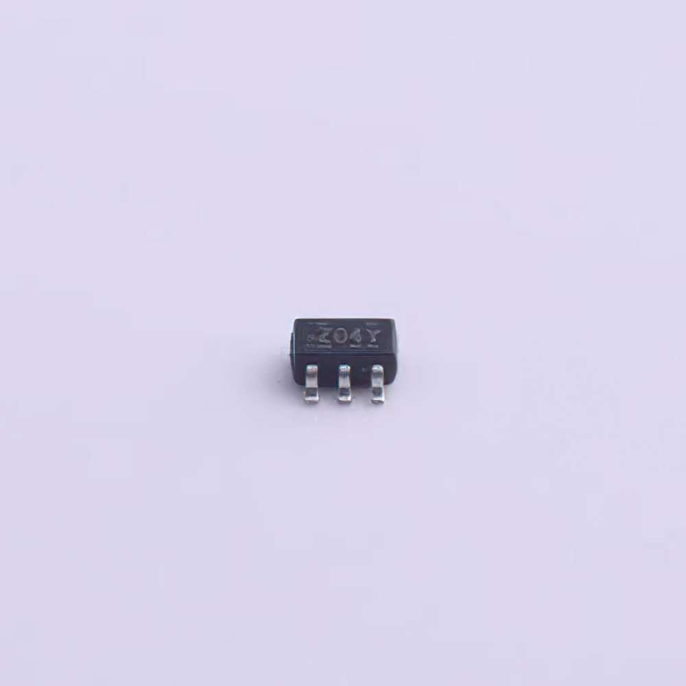
The onsemi NC7WZ04P6X is a widely used device in various digital applications, offering advantages in speed, power efficiency, and reliability. However, like any electronic component, users may encounter some challenges during operation. This article provides a comprehensive guide to troubleshooting and offering solutions for common issues with the NC7WZ04P6X, ensuring that users can get the most out of their device.
Understanding NC7WZ04P6X and Identifying Common Issues
The NC7WZ04P6X is a high-performance CMOS logic gate from ON Semiconductor, designed to offer excellent speed, minimal power consumption, and superior reliability for various digital circuit applications. It is part of the series of inverters, which are essential building blocks in logic design, typically used for signal inversion in applications like timing, data manipulation, and switching. While the NC7WZ04P6X is known for its robust performance, users may sometimes experience issues that affect its functionality. The goal of this article is to provide a step-by-step guide to troubleshooting common problems with the device and presenting solutions to resolve them.
1.1 Overview of NC7WZ04P6X
Before diving into troubleshooting, it's essential to understand the key features of the NC7WZ04P6X:
Type: Inverter
Technology: CMOS (Complementary Metal-Oxide-Semiconductor)
Voltage Supply: Operates over a wide voltage range, typically from 1.65V to 5.5V
Speed: Ultra-high-speed performance (propagation delay time as low as 2ns)
Power Consumption: Low standby current and low power usage make it ideal for power-sensitive applications
Package: Available in various surface-mount packages, including the P6X package type
Due to these excellent characteristics, the NC7WZ04P6X is frequently employed in high-speed logic circuits, timing circuits, and other digital systems where signal integrity is crucial.
1.2 Common Troubleshooting Issues
Issue 1: Incorrect Output Signals
One of the most frequent problems encountered when using the NC7WZ04P6X is incorrect output signals. This issue can manifest as signals not being inverted as expected or the device failing to produce output at all.
Possible Causes:
Incorrect Input Logic: The input to the inverter might not be correctly configured. The NC7WZ04P6X inverts the logic level at its input. If the input is floating or connected to the wrong voltage, the output will also be unpredictable.
Power Supply Instability: A fluctuating or insufficient power supply voltage can cause irregular behavior, leading to malfunctioning outputs.
Faulty Connections: Loose or incorrectly wired connections can lead to no output or erratic signal behavior.
Solution:
Check Input Logic: Ensure the input signal is stable and within the specified voltage range for the device. A logic high (typically above 2V) should result in a low output, and a logic low (below 0.8V) should yield a high output.
Verify Power Supply: Confirm that the device is receiving a stable voltage within the recommended range (1.65V to 5.5V). Any fluctuations outside this range can compromise its performance.
Inspect Wiring: Double-check all connections to ensure there are no shorts or open circuits. It is also a good idea to use a multimeter to test continuity.
Issue 2: Overheating
Overheating is another common issue when using electronic components like the NC7WZ04P6X, especially in high-speed circuits.
Possible Causes:
Excessive Current Draw: If the device is subjected to higher-than-recommended current levels, it can lead to excessive heat generation.
Improper Load Conditions: Connecting the inverter to a load with an incorrect impedance or using it in circuits that require too much current could lead to overheating.
Solution:
Check Load Resistance: Ensure that the output load is within the recommended resistance range and that the current draw does not exceed the specifications.
Heat Dissipation: Improve ventilation around the component or use a heat sink if necessary. Additionally, reducing the switching frequency can lower heat generation.
Use Proper Packaging: If your circuit design includes the NC7WZ04P6X in a densely packed area, consider improving the layout to provide better thermal dissipation.
Issue 3: Signal Integrity Problems
Signal integrity is crucial when using the NC7WZ04P6X, particularly in high-speed circuits. The device’s speed can lead to issues with noise, cross-talk, or reflections, which can degrade performance.
Possible Causes:
Improper PCB Layout: A poorly designed printed circuit board (PCB) layout can lead to signal degradation, especially at high frequencies. Long trace lengths, poor grounding, and inadequate decoupling can all contribute to this problem.
Electromagnetic Interference (EMI): Noise from other components or external sources can affect the integrity of the output signal.
Cross-Talk Between Signals: If signals are not properly shielded or if traces run too closely together, cross-talk can occur, causing unintended interactions between signals.
Solution:
PCB Layout Optimization: Ensure that the PCB layout minimizes long trace lengths, especially for high-frequency signals. Proper grounding and the use of decoupling capacitors can help reduce noise and ensure clean signals.
Shielding and Grounding: Use proper shielding techniques to protect sensitive signals from external EMI. Ground planes and differential signal routing can help minimize noise and signal distortion.
Reduce Trace Crosstalk: Increase the spacing between signal traces, especially high-speed or high-current signals, to reduce the risk of cross-talk. Using a multi-layer PCB with dedicated ground planes can further improve isolation.
Advanced Troubleshooting Tips and Practical Solutions for NC7WZ04P6X
2.1 Power Supply and Voltage Considerations
Power issues are a critical aspect of troubleshooting any CMOS device, including the NC7WZ04P6X. Ensuring the device is receiving clean and stable power is fundamental to its operation.
Issue: Power Supply Fluctuations
Fluctuations in power supply voltage can lead to unexpected behavior in the NC7WZ04P6X, such as erratic output signals or failure to operate.
Solution:
Use Low-Noise Power Supply: Choose a high-quality, low-noise power supply that provides a stable voltage within the recommended range (1.65V to 5.5V). Incorporate a power supply filter or decoupling capacitors close to the NC7WZ04P6X to reduce voltage spikes and noise.
Check for Ground Loops: Ensure that all ground connections are properly routed to prevent ground loops, which can induce noise and power instability.
Issue: Insufficient Voltage Levels
The NC7WZ04P6X requires a minimum input voltage to recognize a logic high level. If the voltage is insufficient, the inverter may not behave as expected.
Solution:
Verify Input Voltage: Ensure that the voltage at the input is high enough for the device to recognize a logic high signal (typically 2V or higher). If your input signal is lower than this threshold, it could result in a malfunction.
Ensure Proper Pull-Up or Pull-Down Resistors : If the input signal is floating, use appropriate pull-up or pull-down resistors to ensure it remains within the expected voltage range.
2.2 External Interference and Electrostatic Discharge (ESD)
Issue: External Interference
The NC7WZ04P6X, being a CMOS device, is highly sensitive to external electromagnetic interference (EMI), which can cause signal degradation or malfunction.
Solution:
Use Proper Shielding: Protect sensitive lines from external interference by using shielding techniques, such as grounding the PCB or placing the device inside a metal enclosure.
Ensure Proper Decoupling: Use decoupling capacitors near the power supply pins to filter out high-frequency noise that may affect device performance.
Issue: Electrostatic Discharge (ESD)
CMOS devices are particularly vulnerable to electrostatic discharge (ESD), which can damage the sensitive internal circuitry of the NC7WZ04P6X.
Solution:
Use ESD Protection: Employ ESD protection components such as diodes or resistors across the input and output pins to protect the device from static discharge.
Handle with Care: Always follow proper ESD precautions when handling the NC7WZ04P6X. Use anti-static wrist straps and mats to prevent electrostatic buildup.
2.3 Advanced Diagnostic Techniques
For more advanced troubleshooting, users can employ diagnostic tools such as oscilloscopes and logic analyzers to get a clearer picture of the device’s operation.
Use of Oscilloscope
An oscilloscope is an invaluable tool for diagnosing issues related to signal integrity, power supply fluctuations, and timing problems.
Solution:
Check Signal Waveforms: Use the oscilloscope to observe the input and output waveforms. Compare the expected inverted output with the actual signal to identify issues.
Measure Timing: Use the oscilloscope to measure propagation delay and ensure that the device is switching at the correct speed. If timing issues arise, check for signal reflections or voltage irregularities.
Use of Logic Analyzer
A logic analyzer can help identify logical errors or timing problems in circuits that use multiple logic gates, including the NC7WZ04P6X.
Solution:
Monitor Digital Signals: A logic analyzer can provide a detailed view of all digital signals in the circuit, allowing you to identify any anomalies or discrepancies in the expected behavior of the NC7WZ04P6X.
Conclusion
While the NC7WZ04P6X is a robust and efficient device, users may encounter various issues related to signal integrity, power supply stability, and external interference. By following the troubleshooting steps outlined in this article, you can ensure that your NC7WZ04P6X operates at peak performance. With proper care, attention to detail, and the use of diagnostic tools, many common issues can be resolved quickly, leading to smoother operation and more reliable circuit designs.
If you're looking for models of commonly used electronic components or more information about NC7WZ04P6X datasheets, compile all your procurement and CAD information in one place.
( Partnering with an electronic component supplier ) sets your team up for success, ensuring that the design, production and procurement processes are streamlined and error-free. ( Contact us ) for free today.

