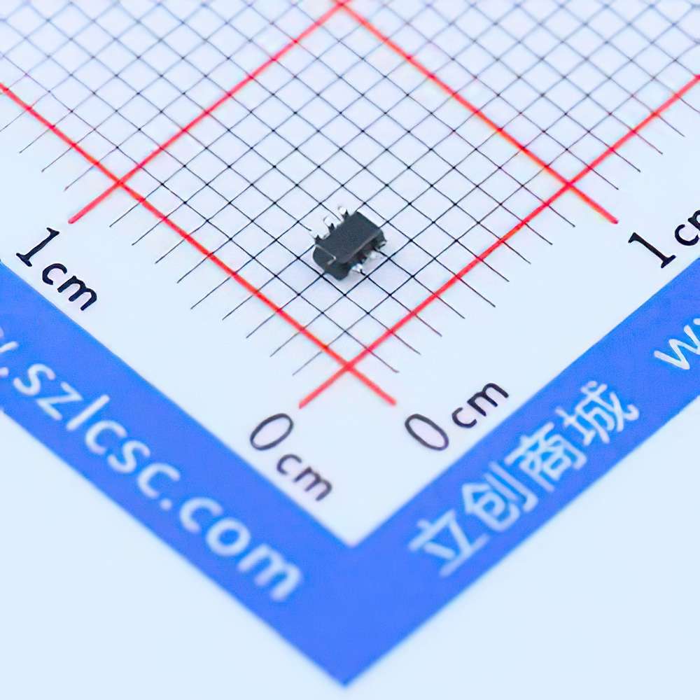
Understanding the SN74LVC1T45DCKR and Common Troubleshooting Scenarios
The SN74LVC1T45DCKR is a versatile, single-channel bidirectional voltage-level translator manufactured by Texas Instruments. Its primary function is to translate logic levels between two different voltage domains. Whether you're working on interfacing systems that operate at 3.3V, 5V, or other voltage levels, this component plays a crucial role in ensuring that signals are correctly interpreted across varying voltage environments. However, like any electronic component, the SN74LVC1T45DCKR can face operational issues. Understanding these potential problems and how to troubleshoot them can save you significant time and effort in your designs.
1. Signal Integrity Issues
One of the most common issues with the SN74LVC1T45DCKR involves signal integrity. This typically manifests as incorrect or intermittent signal translations, leading to unreliable data transmission between systems.
Root Causes
Improper Decoupling: Insufficient decoupling capacitor s or poor placement can cause voltage spikes or noise, leading to signal degradation.
Insufficient Driving Voltage: If the driving signal is too weak or the rise/fall times are too slow, the SN74LVC1T45DCKR may fail to properly interpret the logic level.
Excessive Loading: The device’s output can be negatively affected if there is too much capacitance or load on the output pin, leading to signal attenuation.
Solutions
Proper Decoupling: Ensure that you place capacitors close to the IC pins to filter out noise and smooth voltage fluctuations. A typical setup involves using a 0.1µF ceramic capacitor along with a 10µF bulk capacitor.
Check Drive Strength: Ensure that the input signal has sufficient drive strength and that the rise and fall times are within acceptable ranges. If necessary, use Buffers or drivers to strengthen the input signals.
Reduce Load on Outputs: Minimize the load connected to the device's outputs. Ensure the IC's drive capabilities match the demands of the circuit.
2. Bidirectional Switching Failure
The SN74LVC1T45DCKR is a bidirectional level translator, which means it should automatically sense the direction of signal flow. However, users may experience failures in this bidirectional switching, particularly when working with mixed voltage systems.
Root Causes
Incorrect Pin Connections: Miswiring of the A1 and B1 pins (for bidirectional operation) can prevent proper direction sensing.
Improper Power Supply: Voltage levels on the VCC pins can be mismatched, preventing the device from accurately switching direction.
Insufficient Pull-up/Pull-down Resistors : Without appropriate pull-up or pull-down resistors on the A or B side, the direction of data flow may not be correctly sensed.
Solutions
Check Pin Configuration: Ensure that the A1 and B1 pins are correctly connected, and double-check the orientation of the device. Pay particular attention to the bidirectional direction control pins.
Verify Power Supply Levels: Confirm that the VCC voltage on both sides of the translator is within the specified range for proper switching. Cross-reference this with the datasheet for exact voltage thresholds.
Use Pull-up/Pull-down Resistors: Ensure that pull-up or pull-down resistors are installed where needed, particularly for cases where the device isn’t directly driving a signal but only translating a high-impedance input.
3. Incorrect Voltage Levels
Another common issue is incorrect voltage translation, where the IC might output signals that are either too high or too low for the receiving circuit. This is often caused by mismatched logic levels between the A and B sides or improper setup.
Root Causes
Inconsistent Voltage Supplies: If the power supplies for either side (A or B) are not stable or mismatched, the voltage translation may fail.
Incorrect Logic Input States: Improper input voltage levels on either side of the translator can cause the device to output incorrect logic levels.
Solutions
Check Power Supply Voltages: Use a multimeter to verify the voltage levels at the VCC pins for both sides. Both sides need to be correctly powered for proper operation.
Verify Logic Levels: Ensure that input signals adhere to the voltage levels defined by the datasheet. If necessary, use level shifters on the input side to ensure that the voltage levels are within specification.
4. Device Overheating
Overheating is another potential issue that can arise with the SN74LVC1T45DCKR. Prolonged excessive heat can damage the IC, leading to permanent failure.
Root Causes
Excessive Current: Drawing more current than the device is rated for can cause excessive heating.
Poor PCB Design: Inadequate trace width, insufficient vias for heat dissipation, or poor layout can contribute to overheating.
Ambient Temperature: Operating the device outside the recommended ambient temperature range can lead to thermal issues.
Solutions
Check Current Draw: Ensure that the current drawn by the circuit does not exceed the IC’s maximum specifications. Review the datasheet for the maximum ratings.
Improve PCB Design: Ensure that the PCB has adequate copper area around the device for heat dissipation. Use wider traces or add heat sinks if necessary.
Monitor Temperature: Use thermal sensors to monitor the device's temperature during operation, and ensure it stays within safe limits.
Advanced Troubleshooting Techniques for SN74LVC1T45DCKR
5. Poor Signal Propagation or Latency
Latency and propagation delays are sometimes observed when the SN74LVC1T45DCKR is used in high-speed applications. The device might not perform as expected when it comes to very fast signal transitions or high-frequency operation.
Root Causes
Signal Rise and Fall Times: The IC has a limited response time, and excessive delays in the signal rise and fall times can lead to propagation issues.
Long Trace Lengths: Long PCB traces can introduce parasitic capacitance and inductance, leading to signal delay and reflection.
Capacitive Loading: High capacitive loads on the A or B sides can slow down signal transitions, causing latency in the output.
Solutions
Control Rise and Fall Times: Ensure that the input signal’s rise and fall times are within the acceptable range for the IC. You may need to use series resistors to slow down signal edges or reduce excessive capacitive loading.
Minimize Trace Lengths: Keep trace lengths as short as possible between the IC and other components to minimize signal degradation.
Use Signal Buffers : If dealing with long traces or high-frequency signals, consider using buffers or line drivers to maintain signal integrity.
6. Inconsistent Behavior in Mixed Voltage Environments
In mixed voltage systems, where different parts of the circuit operate at different logic levels (e.g., 3.3V on one side and 5V on the other), users may encounter erratic behavior. The SN74LVC1T45DCKR is designed to handle such environments, but issues can arise if the interface between voltage domains is not properly set up.
Root Causes
Ground Loops: Ground potential differences between the two voltage domains can result in incorrect logic level translations.
Voltage Rail Fluctuations: If either voltage rail fluctuates significantly, the level translator may misinterpret logic levels.
Solutions
Ensure Common Grounding: Always ensure a stable, single-point ground reference between the different voltage domains. Avoid ground loops by connecting all grounds at a single point.
Stabilize Voltage Rails: Use regulators or filters to stabilize voltage levels on both sides of the level translator. Verify that the voltage rails are stable under load.
7. Device Damage from Electrostatic Discharge (ESD)
The SN74LVC1T45DCKR, like many semiconductor components, can be sensitive to electrostatic discharge (ESD), which may cause permanent damage if not properly managed.
Root Causes
Improper Handling: Static electricity from human touch or improperly grounded equipment can discharge into the IC and cause failure.
Lack of Protection: Absence of ESD protection components such as diodes or resistors can leave the device vulnerable to damage.
Solutions
Implement ESD Protection: Use appropriate ESD protection devices such as TVS diodes, resistors, or capacitors to shield the IC from electrostatic discharge.
Follow Proper Handling Protocols: Always use anti-static wrist straps and mats when handling sensitive components to prevent static discharge.
Conclusion
The SN74LVC1T45DCKR is a powerful and reliable component in voltage-level translation, but like all ICs, it requires careful handling and troubleshooting. By understanding common problems such as signal integrity issues, bidirectional switching failures, voltage discrepancies, overheating, and ESD damage, and implementing the outlined solutions, you can ensure optimal performance and longevity for your design. Always refer to the manufacturer’s datasheet for specific guidelines and limitations, and employ best practices in your PCB design to minimize potential issues. By following these steps, you can confidently incorporate the SN74LVC1T45DCKR into your electronic projects without worrying about common pitfalls.
If you are looking for more information on commonly used Electronic Components Models or about Electronic Components Product Catalog datasheets, compile all purchasing and CAD information into one place.

