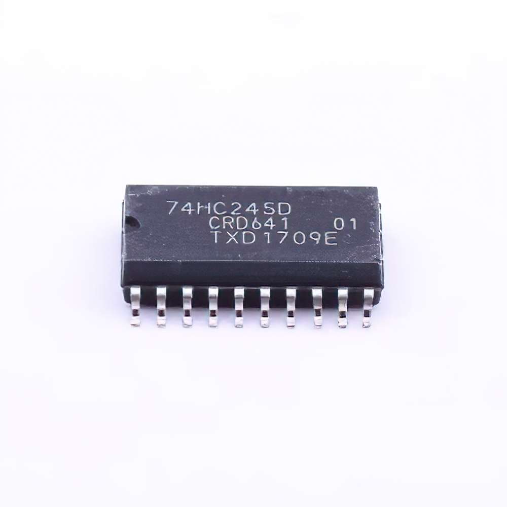
Introduction to 74HC245D in Multi-Channel Signal Bus Switching
In modern digital electronics, the need for efficient and flexible signal routing is more critical than ever. Whether it's for communication systems, testing equipment, or complex embedded systems, multi-channel signal switching plays an essential role in ensuring data flows accurately between different components. The 74HC245D, a high-speed hex buffer/transceiver IC, is one of the most commonly used components for this task. It is especially useful in systems where multiple signals need to be transferred from one bus to another with minimal interference and maximum efficiency.
The 74HC245D belongs to the 74HC series of logic chips, which are part of the high-speed CMOS family. This chip is designed specifically to facilitate bidirectional data transmission between two buses and can be easily interface d with microcontrollers, FPGA circuits, or other digital systems. The 74HC245D allows for both input and output operations in a manner that makes it ideal for applications requiring the switching of multiple channels simultaneously, such as signal routing, multiplexing, and bus isolation.
Key Features of the 74HC245D
Before diving into the implementation and debugging aspects, it is important to understand the core features of the 74HC245D:
Bus Transceiver with 3-State Outputs: The 74HC245D features three-state outputs, which means that it can isolate itself from the bus when not actively driving data, making it ideal for applications where multiple devices share the same data lines.
Bidirectional Data Transfer: One of the standout features of the 74HC245D is its ability to perform bidirectional data transfer. It allows signals to flow in either direction, depending on the control inputs, which makes it perfect for multi-channel applications that require flexible data routing.
High-Speed Operation: Operating at up to 30 MHz, the 74HC245D is capable of handling high-speed data transfer, making it suitable for systems with demanding bandwidth requirements.
Low Power Consumption: Like many CMOS devices, the 74HC245D consumes minimal power during operation, making it well-suited for battery-powered systems and portable devices.
Wide Voltage Range: With an operating voltage range of 2V to 6V, the 74HC245D is adaptable to a variety of digital systems, from low-voltage logic circuits to standard 5V TTL systems.
Implementing 74HC245D for Multi-Channel Signal Bus Switching
Implementing the 74HC245D in a multi-channel signal bus switching application requires careful planning and understanding of both the chip’s functionality and the overall system design. Here's a breakdown of the steps and considerations for successful implementation.
System Design Considerations:
The first step in the implementation process is to map out the system's requirements and determine the number of channels that need to be switched. The 74HC245D offers eight data pins, so multiple ICs may be required for larger buses or more complex systems. In this stage, it’s also important to consider whether the system requires bidirectional or unidirectional data flow.
Signal Routing:
The 74HC245D can be used to route signals between different buses or subsystems. By using its control pins (DIR and OE), you can configure the chip to drive signals in one direction (towards the bus or away from it). For bidirectional systems, careful planning of the control logic is necessary to ensure that signals flow correctly based on the system’s needs.
Controlling the Direction Pins (DIR and OE):
The key to controlling the flow of data in multi-channel switching systems is understanding how to use the DIR (direction) and OE (output enable) pins. The DIR pin determines the direction of data flow, while the OE pin enables or disables the output drivers. When OE is high, the output drivers are disabled, and the device is effectively isolated from the bus. By configuring these pins appropriately, you can set up a reliable switching network.
Clock Synchronization:
In multi-channel systems, signal synchronization is critical to avoid data corruption or timing mismatches. When using the 74HC245D, ensure that the clock signals for each channel are synchronized, particularly when handling bidirectional data. Depending on the complexity of your system, you may need to implement additional clock management ICs or techniques to ensure smooth data transfer.
Power Considerations:
While the 74HC245D is known for its low power consumption, you must ensure that the power requirements of all connected components are met. Proper decoupling capacitor s should be placed near the IC to reduce noise and ensure stable operation. Additionally, consider the power supply’s voltage level, as the 74HC245D operates best within its specified voltage range.
Common Challenges in Multi-Channel Signal Switching
Despite the many advantages of the 74HC245D, implementing it in complex signal bus systems comes with its own set of challenges:
Signal Integrity: One of the most common challenges when using the 74HC245D in multi-channel systems is maintaining signal integrity. Proper PCB design, trace routing, and grounding are essential to minimize interference and signal degradation, especially in high-speed applications.
Controlling Multiple ICs: When dealing with a larger number of channels, multiple 74HC245D ICs may be required. Coordinating their operation can be complex, particularly when managing the control signals for the direction and output enable pins.
Electromagnetic Interference (EMI): In systems with high-speed data transfer, EMI can be a significant concern. The design must minimize the risk of EMI by careful routing of traces, proper shielding, and grounding.
Thermal Management : Although the 74HC245D has low power consumption, in high-density systems or those operating at high frequencies, thermal management becomes important. Ensure that the ICs are adequately spaced and that the system has sufficient cooling.
Debugging and Troubleshooting 74HC245D in Multi-Channel Applications
While implementing the 74HC245D can be straightforward for basic applications, debugging and troubleshooting can sometimes be tricky, especially in more complex systems. Here’s a guide to help identify and resolve common issues that may arise during development.
Checking Pin Connections:
The first step in troubleshooting any circuit is to verify that all pin connections are correct. Start by double-checking the connections for the power supply, ground, and control pins (DIR and OE). Incorrect or floating connections can cause erratic behavior and lead to misrouted signals or complete system failure.
Testing Control Signals:
For the 74HC245D to operate correctly, the DIR and OE pins must be controlled properly. Use an oscilloscope or logic analyzer to verify the timing and state of these pins. If the DIR pin is not toggling correctly, data may not flow in the desired direction. Similarly, if the OE pin is not being driven high or low as expected, the IC may not output data, or it could be outputting data when it shouldn’t.
Signal Monitoring:
To troubleshoot signal integrity, use an oscilloscope to monitor the signals on the data pins. Look for signs of noise, glitches, or delays that could indicate issues with trace routing, improper voltage levels, or signal reflection. If the signal appears distorted or inconsistent, consider adjusting the PCB layout, improving the grounding, or adding series termination resistors.
Voltage Level Checks:
Ensure that the input and output voltage levels are within the specified range for the 74HC245D. If the voltage levels are too high or too low, the IC may not function as expected. Check the datasheet for the recommended voltage levels and ensure that the system’s supply voltage is stable.
Isolating Faulty ICs:
In systems with multiple 74HC245D ICs, it can be challenging to pinpoint which one is causing the problem. One useful technique is to isolate sections of the circuit by temporarily disconnecting or disabling specific ICs. This can help you identify whether a particular IC is malfunctioning or if the issue lies in the wiring or control logic.
Timing Issues:
Timing is critical in multi-channel systems, and timing errors can lead to data corruption or misrouting. Ensure that the clock signals for the 74HC245D are stable and that the data transfer timing is in sync with other components in the system. Use timing diagrams to compare the expected and actual behavior of the system to identify discrepancies.
Temperature Monitoring:
Overheating can cause unpredictable behavior in digital circuits. If the system operates at high frequencies or with a large number of channels, monitor the temperature of the 74HC245D and its surrounding components. If the temperature exceeds the safe operating range, consider improving cooling or reducing the system's power consumption.
Conclusion
The 74HC245D is a versatile and reliable IC for multi-channel signal bus switching applications. With its bidirectional data transfer capabilities, high-speed performance, and low power consumption, it offers an ideal solution for systems requiring flexible signal routing. However, successful implementation and debugging require careful planning, attention to detail, and systematic troubleshooting. By understanding the key features of the 74HC245D and following best practices for design and debugging, engineers can ensure optimal performance and reliability in their signal switching systems.
Partnering with an electronic components supplier sets your team up for success, ensuring the design, production, and procurement processes are quality and error-free.

