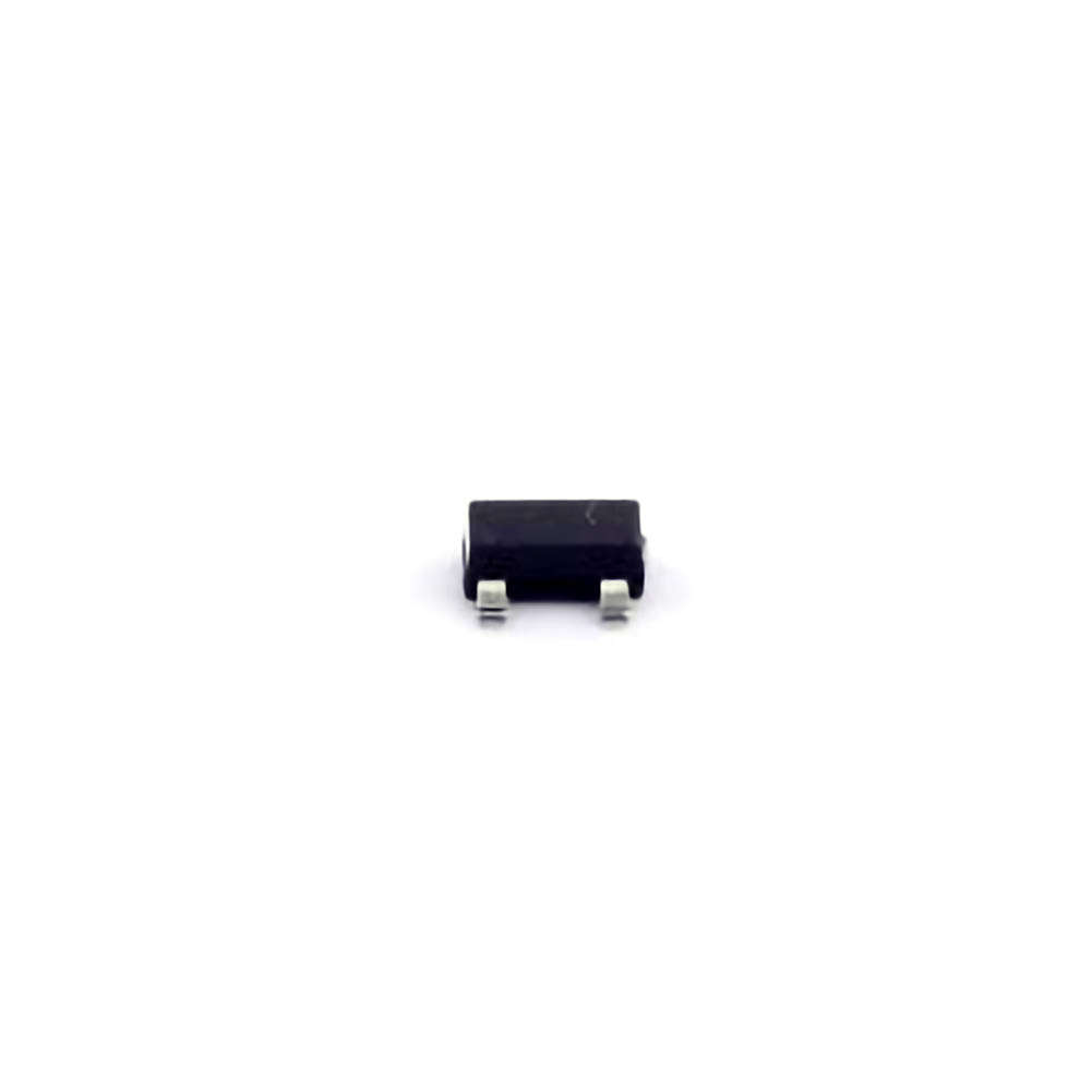
Understanding the CDSOT23-SM712 and Common Troubleshooting Issues
The BOURNS CDSOT23-SM712 is a surface-mount transient voltage suppressor ( TVS ) Diode designed to protect sensitive electronic components from voltage spikes and transient overvoltages. It’s a key component in circuits where protection against ESD (electrostatic discharge) and other transient events is necessary. Although the CDSOT23-SM712 is a reliable and durable device, it is not immune to failures or issues that might arise during its integration into a circuit. In this part, we will explore the general functionality of the CDSOT23-SM712 and highlight some common troubleshooting issues.
1.1 Functionality of the CDSOT23-SM712
The CDSOT23-SM712 is designed to clamp transient voltages and prevent them from reaching a level that could potentially damage the sensitive parts of an electronic system. It features a low clamping voltage, which makes it ideal for protecting sensitive digital circuits, communication ports, and power supply lines.
Its key attributes include:
Reverse Stand-Off Voltage: The CDSOT23-SM712 can withstand voltages up to a specific threshold (7V in this case) before clamping occurs.
Clamping Voltage: When the transient voltage exceeds the reverse stand-off voltage, the diode starts conducting and limits the voltage, protecting the circuit.
Low Capacitance: This ensures minimal signal distortion, making it especially useful in high-speed data transmission systems.
These attributes make the device highly efficient for protecting against electrical surges, but it’s crucial to ensure proper installation and circuit design for optimal performance.
1.2 Common Troubleshooting Issues
Despite its reliable performance, several common issues may arise with the CDSOT23-SM712 that can affect its functionality. Let’s explore these issues and how to diagnose them:
1.2.1 Incorrect Placement in the Circuit
One of the most common issues with any surface-mount component is incorrect placement on the PCB (Printed Circuit Board). The CDSOT23-SM712 is typically mounted across sensitive components or inputs, such as data lines or power rails. If it is incorrectly placed (for example, in the wrong orientation or on an incorrect trace), it will fail to provide the necessary protection.
Solution:
Double-check the schematic and the PCB layout to ensure that the device is placed in the correct orientation.
Confirm that the cathode (negative side) is connected to the higher voltage side (usually the ground), and the anode (positive side) is connected to the input line.
1.2.2 Clamping Voltage Too High
If the clamping voltage of the CDSOT23-SM712 is too high, it might not provide adequate protection during a transient event. This can happen due to manufacturing defects or improper selection of components for the circuit.
Solution:
Measure the voltage across the diode during a transient event to ensure it is clamping within the rated limits (usually below 7V). If it is higher, replace the component with a new one.
Ensure that the circuit design specifies the correct TVS diode for the voltage levels in your application. Selecting a diode with a lower clamping voltage might be necessary for more sensitive circuits.
1.2.3 Overstress Due to High Energy Events
The CDSOT23-SM712 is designed to handle typical transient events, but if it is subjected to high-energy events, such as severe ESD or lightning strikes, it may become damaged. In these cases, the diode may fail to clamp properly or could experience permanent breakdown.
Solution:
If you notice a complete failure of the diode (open circuit or shorted), it’s likely that the component has been overstressed. Replace the diode with a new one and consider adding additional protection (e.g., more robust diodes or an RC snubber circuit) if your circuit is exposed to higher-than-expected transient events.
Always ensure that the TVS diode is chosen based on the expected surge energy and clamping power for your specific application.
1.2.4 Degradation Over Time
As with any electronic component, the performance of the CDSOT23-SM712 may degrade over time, especially if it has been exposed to repeated transient events. The diode may lose its ability to clamp effectively, or it might show signs of increased leakage current, meaning it no longer offers the same level of protection.
Solution:
Regularly inspect and test the diode during routine maintenance checks.
Use a multimeter or specialized testing equipment to measure leakage current and ensure it’s within the specified range. If the leakage is high, replace the diode.
Implement preventive measures such as improving grounding or adding series resistors to reduce the frequency of high-energy spikes.
1.3 Diagnostic Tools for Troubleshooting
To effectively troubleshoot the CDSOT23-SM712, it is important to use the correct diagnostic tools. Here are some tools and techniques that can help identify issues quickly:
Multimeter: Measure the diode's forward voltage and leakage current. A healthy TVS diode should show a low forward voltage when tested in one direction and should block current when tested in the reverse direction.
Oscilloscope: Capture transient spikes and verify if the clamping voltage is functioning within expected limits during transient events.
Component Tester: Use a specialized component tester to check the integrity and clamping behavior of the diode before and after installation.
Solutions for Resolving CDSOT23-SM712 Troubleshooting Problems
In part 1, we explored the common issues faced when working with the CDSOT23-SM712, such as incorrect placement, high clamping voltage, overstress damage, and degradation over time. Now, let’s look at effective solutions and strategies for resolving these problems and ensuring that your CDSOT23-SM712 provides reliable protection in your circuits.
2.1 Ensuring Proper Circuit Design and Component Selection
One of the most effective ways to avoid troubleshooting issues with the CDSOT23-SM712 is through proper circuit design and component selection. A well-designed circuit will minimize the risks of overstress and ensure that the transient voltage suppressor performs as expected.
2.1.1 Correct Selection of TVS Diode
Ensure that the CDSOT23-SM712 is suitable for your application by confirming that the reverse standoff voltage is appropriate for your system. For circuits with higher voltage levels, you might need to use a higher-voltage TVS diode or one with a higher clamping capability.
Solution:
Review your system’s operating voltage and select a TVS diode that can withstand transient voltage spikes without damage.
Consider multiple stages of protection, such as using higher-rated diodes for heavy transients and the CDSOT23-SM712 for lower, more frequent events.
2.1.2 Circuit Layout Considerations
Proper placement of the TVS diode is critical. Place the CDSOT23-SM712 as close as possible to the point of vulnerability, such as sensitive signal inputs or power rails.
Solution:
Follow best practices for PCB layout by keeping the leads short and minimizing the path of the transient current.
Use a ground plane to ensure efficient clamping and to minimize the risk of signal interference or cross-talk.
2.2 Routine Maintenance and Testing
One of the best ways to prevent issues with the CDSOT23-SM712 is through regular maintenance and testing. Ensure that your circuit is not exposed to frequent overvoltage conditions that could degrade the performance of the TVS diode.
2.2.1 Periodic Testing
Periodic testing of your circuit components will ensure that everything is functioning properly. Check the diode’s clamping voltage and measure the leakage current at regular intervals, especially if the circuit is exposed to frequent transients.
Solution:
Perform routine inspections of the TVS diode after each significant transient event (e.g., a lightning strike or power surge) to verify its continued functionality.
Replace any diode showing signs of wear or damage to avoid the risk of failure.
2.2.2 Implementing Additional Protection
If your circuit is prone to high-voltage spikes or frequent transients, consider using additional protection to ensure the CDSOT23-SM712 is not overstressed.
Solution:
Use multiple TVS diodes in series or parallel to handle higher surge energy.
Add fuses or resistors in line to limit the current entering the TVS diode during a transient event.
2.3 Post-Failure Recovery
If the CDSOT23-SM712 fails despite best practices, recovery is straightforward with the right tools. Begin by identifying the cause of failure (overvoltage, incorrect placement, etc.) and replace the faulty component.
Solution:
Carefully remove the faulty CDSOT23-SM712 from the PCB and solder a new one into place.
Re-test the circuit after replacement and perform any necessary adjustments to prevent similar failures in the future.
By carefully following these troubleshooting tips and maintenance practices, you can significantly extend the lifespan and reliability of the CDSOT23-SM712 in your circuits.
If you are looking for more information on commonly used Electronic Components Models or about Electronic Components Product Catalog datasheets, compile all purchasing and CAD information into one place.


