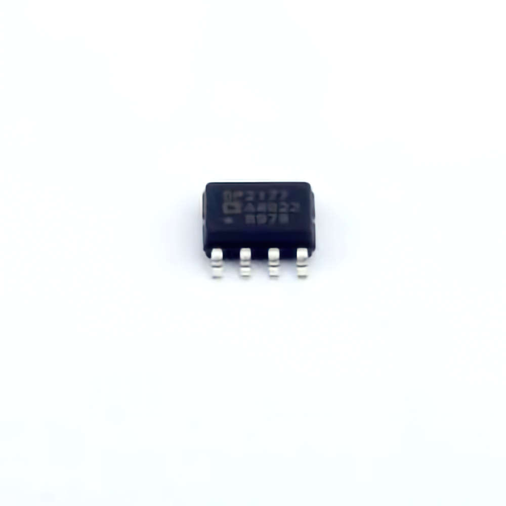
Understanding the OP2177ARZ and Common Troubleshooting Issues
The ADI OP2177ARZ, a precision operational amplifier from Analog Devices, is known for its low noise, high accuracy, and excellent offset voltage characteristics. It is widely used in industrial, automotive, medical, and consumer electronics. However, like all electronic components, it may encounter performance issues that need troubleshooting. Identifying the root cause of these problems early on can save time and resources while ensuring the longevity of the device. This article will outline common issues that users might face when working with the OP2177ARZ and offer actionable solutions to resolve them effectively.
1. Understanding the OP2177ARZ
Before diving into troubleshooting, it's crucial to understand the basic functionality of the OP2177ARZ. This dual operational amplifier is designed for applications that require high precision and low drift. Its low offset voltage (25 µV max) and low bias current (1 pA max) make it ideal for sensitive applications such as signal conditioning, measurement systems, and data acquisition. It is often used in high-performance analog circuits where accuracy is paramount.
Despite its robust design and superior performance characteristics, the OP2177ARZ can encounter a variety of issues that may affect its operation. Below, we explore some of the most common troubleshooting problems.
2. Problem 1: High Offset Voltage or Drift
One of the most significant challenges users might face with the OP2177ARZ is high offset voltage or drift. Offset voltage refers to the difference between the ideal zero voltage input and the actual output of the operational amplifier when both inputs are grounded. Drift occurs when the offset voltage changes over time due to temperature fluctuations, aging, or Power supply variations.
Troubleshooting Steps:
Check the Power Supply: Ensure that the power supply voltage is stable and within the specified range for the OP2177ARZ. Voltage fluctuations can cause offset voltage drift.
Monitor Temperature Changes: The OP2177ARZ has a specified temperature coefficient for offset voltage, which can affect performance under extreme temperature conditions. Make sure the IC is operating within the recommended temperature range of -40°C to +125°C.
Use Precision Potentiometers for Calibration: In cases where the offset is critical, use external trimming components like potentiometers to fine-tune the offset voltage.
Ensure Proper PCB Layout: A poor PCB layout can introduce noise or parasitic elements that exacerbate offset issues. Keep the layout clean and ensure proper grounding.
3. Problem 2: Oscillation or Instability
The OP2177ARZ is designed to be stable across a wide range of frequencies, but improper circuit design or parasitic capacitances can cause oscillations or instability. Oscillations can manifest as unwanted high-frequency noise or fluctuations at the output, which can render the operational amplifier unsuitable for high-precision tasks.
Troubleshooting Steps:
Check for Adequate Bypass capacitor s: Adding decoupling capacitors near the power pins of the OP2177ARZ can help stabilize the voltage supply and minimize noise. Typically, 0.1µF ceramic capacitors are used in parallel with a larger 10µF capacitor.
Review Circuit Gain and Bandwidth: Ensure that the gain and bandwidth of the operational amplifier are within specifications. Excessive gain can cause oscillations, especially when the amplifier is driving capacitive loads.
Minimize Parasitic Capacitance: Parasitic capacitance from the PCB or surrounding components can lead to oscillations. Use short, direct signal paths and avoid routing sensitive traces near high-speed signal traces.
Check for Proper Compensation: In some cases, additional compensation may be needed to ensure stability. Ensure that your design includes the appropriate compensation for the desired operating conditions.
4. Problem 3: Output Saturation
When the OP2177ARZ’s output voltage reaches the rails of the power supply (i.e., it saturates), it can cause significant issues in the performance of the circuit. Output saturation can occur due to an incorrect feedback loop, excessive input voltage, or an imbalanced input differential voltage.
Troubleshooting Steps:
Examine the Feedback Network: Ensure that the feedback resistor network is correctly sized. Incorrect feedback can lead to improper output voltage behavior.
Ensure Input Voltage Compliance: Verify that the input voltage is within the specified common-mode input range. Exceeding this range can cause the amplifier to saturate.
Check Load Resistance : A low load resistance can place excessive demand on the operational amplifier’s output stage, leading to saturation. Ensure that the load impedance is within the recommended range.
Increase the Headroom: If the amplifier is working close to the supply rails, consider increasing the supply voltage or using a rail-to-rail output amplifier if the application requires operation closer to the rails.
5. Problem 4: Excessive Power Consumption
While the OP2177ARZ is designed for low power consumption, excessive current draw can still occur in certain situations. This can happen due to incorrect power supply connections, improper grounding, or high-frequency oscillations that lead to increased power dissipation.
Troubleshooting Steps:
Verify Power Supply Connections: Double-check the power connections to ensure the correct voltage is applied, and that there are no short circuits or improper connections that could cause increased current draw.
Review the Output Stage Load: Driving a highly capacitive load or a low impedance load can cause higher current consumption. Ensure the output stage is matched appropriately to the load.
Measure Quiescent Current: Use a multimeter to measure the quiescent current (idle current) of the OP2177ARZ. If the current is abnormally high, inspect for signs of faulty components or short circuits.
Advanced Troubleshooting and Long-Term Solutions for OP2177ARZ Issues
While the common problems discussed in Part 1 can usually be addressed with straightforward solutions, there are additional advanced troubleshooting techniques and long-term strategies to ensure the OP2177ARZ remains in optimal condition throughout its service life. These strategies focus on mitigating recurring issues, improving overall system stability, and preventing component degradation over time.
6. Problem 5: Input Bias Current and Its Impact
Input bias current refers to the small current that flows into the inputs of the operational amplifier. While the OP2177ARZ is designed to minimize input bias current, it can still create issues, particularly in high-impedance applications. If not managed properly, input bias current can result in offset voltage and errors in sensitive measurements.
Troubleshooting Steps:
Use Bias Compensation: One effective way to address input bias current is to use compensation resistors at the input. This technique can nullify the impact of bias current by creating a matched impedance at both the inverting and non-inverting inputs.
Implement Low-Resistance Paths: Reducing the resistance between the input pins and ground can help minimize the effect of input bias currents. Low-resistance paths decrease the potential difference caused by the bias current, improving accuracy.
Choose Proper Input Components: In some cases, using low-bias current sensors or input stages with higher impedance may help alleviate the issue of input bias current.
7. Problem 6: ESD (Electrostatic Discharge) Sensitivity
While the OP2177ARZ is generally resistant to damage, electrostatic discharge (ESD) can still damage sensitive pins or degrade the long-term performance of the IC. Users working in environments with high levels of static electricity need to be cautious when handling and integrating the component.
Troubleshooting Steps:
Use ESD Protection: Always ensure that ESD protection components, such as diodes or transorbs, are placed near vulnerable pins to absorb excessive voltage spikes.
Implement Proper Handling Protocols: When working with the OP2177ARZ, use anti-static wrist straps, mats, and other grounding techniques to minimize the risk of static discharge during installation or testing.
Increase PCB Grounding: A well-grounded PCB layout can help dissipate electrostatic charges before they affect the operational amplifier.
8. Long-Term Solutions for Maintaining OP2177ARZ Performance
To ensure the OP2177ARZ operates efficiently for an extended period, follow these best practices:
Use High-Quality Components: Choose high-quality capacitors, resistors, and other supporting components to ensure long-term stability and reliability.
Implement Regular Calibration: Depending on the application, calibrating the OP2177ARZ periodically can help maintain its precision and accuracy over time.
Ensure Robust Circuit Design: A robust, well-tested design will minimize the likelihood of circuit issues and enhance the OP2177ARZ's long-term performance.
By understanding and addressing these common troubleshooting challenges, users can ensure their OP2177ARZ operational amplifiers function at peak performance. Through careful selection of components, appropriate circuit design, and ongoing maintenance, you can significantly extend the life and reliability of this essential IC.
Partnering with an electronic components supplier sets your team up for success, ensuring the design, production, and procurement processes are quality and error-free.


