Understanding the FSA2567MPX and Common Troubleshooting Scenarios
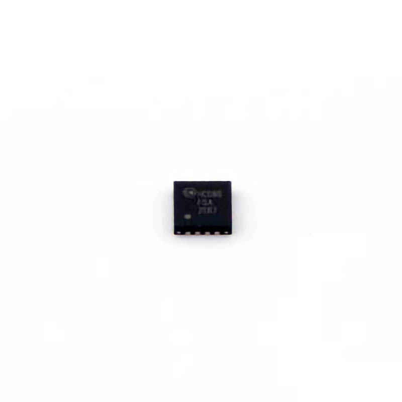
The ons EMI (Ansemi) FSA2567MPX is a popular integrated circuit (IC) used in various electronic devices for signal switching and routing. Its versatile functionality makes it a go-to choice for many engineers working in fields like audio processing, Communication s, and consumer electronics. However, as with all electronic components, problems can arise, and understanding how to troubleshoot them efficiently is critical.
1.1 Overview of the FSA2567MPX
The FSA2567MPX is an analog multiplexer designed for high-pe RF ormance switching applications. It allows multiple signals to pass through a single line, offering users the flexibility to manage several inputs and outputs. This IC features low Power consumption, a broad operating voltage range, and high signal integrity, making it suitable for a variety of applications including audio, video, and data communications.
Despite its reliable performance, users sometimes experience issues that can hinder its functionality. Identifying and resolving these issues requires knowledge of the component’s design and common failure points.
1.2 Power Supply Issues: The Root of Many Problems
One of the most common issues with the FSA2567MPX is power supply-related problems. The IC requires a stable voltage supply to function properly, and fluctuations or interruptions in power can lead to malfunctioning of the device.
Symptoms of Power Supply Issues:
The IC fails to switch between channels.
Signal output is distorted or absent.
The IC becomes hot to the touch.
Solutions:
Check Voltage Levels: Use a multimeter to verify that the supply voltage to the FSA2567MPX is within the specified range (typically between 2.7V to 5.5V). Ensure that there are no voltage spikes or drops that might cause instability.
Inspect Power Sources: If the power supply is shared with other components, ensure that the overall system is not drawing too much current, which could lead to undervoltage at the IC.
Consider Using Decoupling Capacitors : Place capacitor s near the power pins of the IC to filter out any high-frequency noise and smooth voltage fluctuations.
1.3 Signal Integrity Issues
The FSA2567MPX is designed for high-speed signal routing, but signal degradation can occur if there is improper grounding, excessive noise, or other interference.
Symptoms of Signal Integrity Problems:
Distorted or noisy signal outputs.
Drop in signal quality or volume.
Communication failure in data transmission applications.
Solutions:
Check Grounding: Ensure that the IC’s ground is properly connected and that there is no loose or broken connection. Grounding issues can introduce noise into the signal path.
Use Shielding: In environments with high electromagnetic interference (EMI), consider using shielding to protect the IC from external noise.
Keep Signal Paths Short and Direct: Minimize the length of signal traces on the PCB to reduce signal loss and prevent unwanted signal reflection.
1.4 Configuration and Control Line Issues
The FSA2567MPX is controlled via external logic signals, which determine which channels are active. Issues with these control lines can prevent the IC from switching channels as expected.
Symptoms of Control Line Issues:
The IC does not respond to changes in control signals.
Incorrect channels are activated.
No signal output despite control line activity.
Solutions:
Verify Control Signals: Use an oscilloscope to monitor the control signals (S0, S1, etc.). Ensure that they match the expected levels and Timing as per the datasheet.
Check for Logic Level Mismatches: If the IC is driven by logic levels incompatible with the FSA2567MPX, it may fail to recognize control signals. Ensure that the control voltage is within the acceptable range.
Inspect for Short Circuits or Open Circuits: Look for any short circuits or broken connections on the control lines that could affect signal transmission.
1.5 Overheating and Thermal Management
Overheating is a critical issue that can cause the FSA2567MPX to malfunction or even permanently fail. Excessive heat buildup typically results from poor thermal management or excessive current draw.
Symptoms of Overheating:
The IC becomes uncomfortably hot to the touch.
Reduced performance or erratic behavior.
Complete failure of the IC if the temperature exceeds safe limits.
Solutions:
Improve Heat Dissipation: Ensure that the IC is not operating in a confined space with poor airflow. Consider using heat sinks or increasing PCB copper area to enhance heat dissipation.
Limit Power Consumption: Check if the IC is being operated at excessive current levels. Reducing the load or optimizing power distribution can help mitigate overheating.
Use Temperature Sensors : Incorporate temperature sensors in the design to monitor the IC’s temperature. If the temperature exceeds safe limits, the system can automatically shut down or enter a safe mode.
1.6 Faulty or Damaged Components
Finally, damaged or faulty components can also contribute to the failure of the FSA2567MPX. This could include physical damage to the IC itself, nearby components, or even soldering issues.
Symptoms of Component Damage:
The IC does not power up or function at all.
Intermittent failures that occur after the device has been in use for some time.
Visible physical damage such as burn marks or broken pins.
Solutions:
Inspect for Physical Damage: Visually inspect the IC and surrounding components for signs of physical damage. If the IC appears damaged, it may need to be replaced.
Check for Soldering Issues: Poor solder joints can lead to intermittent contact and unreliable performance. Reflow any suspect solder joints and ensure good connection quality.
Replace Damaged Components: If the IC itself is damaged, replace it with a new one. If other components are found to be faulty, replace them as needed.
Advanced Troubleshooting and Long-Term Solutions for the FSA2567MPX
Once you’ve addressed the more common issues with the FSA2567MPX, it’s time to move into more advanced troubleshooting techniques. These steps involve diagnosing more complex problems that may not be immediately apparent or easily fixed.
2.1 Signal Distortion and Crosstalk
Signal distortion and crosstalk between channels can occur when signals bleed over into neighboring channels, affecting overall performance.
Symptoms of Crosstalk and Distortion:
Signals from adjacent channels interfere with one another.
The signal becomes unstable or garbled.
Unexpected switching behavior.
Solutions:
Check Channel Isolation: Ensure that the IC’s switching mechanism is isolating channels as intended. Poor isolation could be a sign of internal damage or a configuration error.
Examine PCB Layout: Improper PCB layout can lead to crosstalk. Ensure that signal traces are routed away from each other and that adequate spacing is maintained to minimize the possibility of signal coupling.
Use Ground Planes: Implementing solid ground planes on the PCB can help reduce the likelihood of signal crosstalk by providing a return path for signals and shielding against external noise.
2.2 Software and Firmware Conflicts
In many applications, the FSA2567MPX is controlled by a microcontroller or processor. Software or firmware issues can lead to problems with how the IC operates.
Symptoms of Software Issues:
The IC behaves unpredictably in response to control inputs.
Channel selection does not correspond to the expected values.
Timing issues arise when switching between channels.
Solutions:
Review the Firmware Code: Check the software or firmware controlling the FSA2567MPX for logical errors. Ensure that the control signals are being set correctly and that timing constraints are met.
Ensure Proper Timing: Timing mismatches between control signals and the IC’s switching process can cause issues. Verify that the software generates control signals with appropriate timing for the IC.
Test in a Simulated Environment: If possible, use a software simulation to test the behavior of the IC before implementing it in a live system. This can help catch potential issues early.
2.3 Interference from External Sources
External electromagnetic interference (EMI) or radio-frequency interference (RFI) can disrupt the performance of the FSA2567MPX, especially in high-frequency applications like communications.
Symptoms of Interference:
Unstable or noisy output.
Unexplained behavior that seems to change with environmental conditions.
Signal degradation in high-speed data applications.
Solutions:
Improve Shielding: If EMI or RFI is suspected, increase the shielding around the device. Use metal enclosures or conductive coatings to prevent interference from entering the signal path.
Use Ferrite beads : Place ferrite beads on power and signal lines to filter out high-frequency noise that might affect the IC.
Minimize External Noise Sources: Ensure that sources of interference, such as high-power transmitters or large electrical equipment, are kept as far from the FSA2567MPX as possible.
2.4 Long-Term Reliability Considerations
For long-term reliability, it is essential to maintain the proper operating conditions for the FSA2567MPX and prevent issues from occurring over time.
Solutions for Long-Term Reliability:
Regular Maintenance and Inspection: Periodically check the IC’s performance, power supply, and connections to ensure everything remains in good working condition.
Use ESD Protection: Incorporate electrostatic discharge (ESD) protection in your design to safeguard the FSA2567MPX from sudden voltage spikes.
Choose High-Quality Components: Use high-quality components that match the specifications for the FSA2567MPX to ensure that the overall system performs optimally and reliably.
By addressing both common and advanced troubleshooting steps, you can significantly reduce the likelihood of issues with the FSA2567MPX and ensure that it functions smoothly in your applications. Whether you’re dealing with power issues, signal integrity, or interference, a systematic approach to troubleshooting can save time and effort, leading to more reliable and efficient designs.
This concludes our in-depth look at troubleshooting the FSA2567MPX. By following these steps and solutions, you can quickly diagnose and address the most common problems, ensuring the long-term success of your project.
If you are looking for more information on commonly used Electronic Components Models or about Electronic Components Product Catalog datasheets, compile all purchasing and CAD information into one place.


