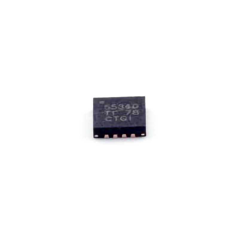
Understanding the TPS55340RTER and Common Issues
The TPS55340RTER is a highly efficient buck-boost DC-DC converter, designed by Texas Instruments to deliver a regulated output voltage in both step-up and step-down configurations. It supports a wide input voltage range (2.95V to 16V), making it ideal for applications where the input voltage may vary or fluctuate, such as portable devices, automotive systems, and industrial control systems. The device integrates a 4A peak current mode controller, providing excellent pe RF ormance for demanding applications that require both high efficiency and precision.
While the TPS55340RTER is a robust and reliable component, users may occasionally encounter issues during its implementation. Troubleshooting these problems requires a clear understanding of the converter’s design and operational parameters. Below, we’ll examine the most common problems associated with the TPS55340RTER, as well as their solutions.
1. No Output Voltage or Incorrect Output Voltage
One of the most common issues with any Power supply is the absence of the expected output voltage or an incorrect voltage. In the case of the TPS55340RTER, this can happen due to several factors:
Incorrect Input Voltage: The TPS55340RTER operates within a defined input voltage range of 2.95V to 16V. If the input voltage falls outside this range, the converter may fail to regulate the output properly. Ensure that the input voltage is stable and within the specified limits.
Inadequate External Components: The TPS55340RTER requires specific external components, such as Inductors , capacitor s, and resistors, to function correctly. Incorrect component values or poor-quality components can result in improper operation. Check the datasheet for the recommended values and specifications for each component, and verify that they are correctly installed.
Faulty Connections: Loose or broken connections, especially in high-current paths, can cause voltage drops or a complete lack of output. Double-check all solder joints, traces, and connectors for any signs of wear or poor connections.
Overvoltage or Undervoltage Protection: If the TPS55340RTER is designed with overvoltage or undervoltage protection, it may shut down or enter a fault mode when the output exceeds or falls below the designated thresholds. Check the status of the EN (Enable) pin and any other fault-detection pins to ensure the device is not in a protection state.
Faulty Internal Components: If all external factors are in check but the output is still incorrect, the internal circuitry of the device might be faulty. In this case, replacement of the TPS55340RTER may be necessary.
Solution: Verify the input voltage range, check the external components for correctness and quality, and inspect the connections. If the issue persists, test the device with known-good components or replace the converter.
2. Overheating of the TPS55340RTER
Another issue that can arise with the TPS55340RTER is excessive heat generation. Overheating can lead to thermal shutdown or permanent damage to the converter. The device is designed with thermal protection, but prolonged exposure to high temperatures can cause performance degradation.
Several factors contribute to overheating:
Excessive Load Current: If the output current drawn by the load exceeds the device’s rated output current, it can cause the converter to work harder than it is designed to, leading to excessive heat buildup. Ensure that the load is within the specified current limits.
Poor Thermal Design: Insufficient cooling, inadequate PCB layout, or poor thermal management practices can result in higher-than-expected temperatures. The TPS55340RTER requires a well-designed PCB with proper heat dissipation channels and sufficient copper area for heat spreading.
Inadequate Inductor and Capacitor Selection: The choice of inductor and Capacitors plays a critical role in the efficiency and thermal performance of the converter. Using components that are not optimized for the required frequency or current can result in higher losses and, consequently, higher temperatures.
Solution: Reduce the load current to within the device's specifications. Ensure proper PCB layout and thermal design, including adequate heat sinking and proper placement of components. Use high-quality, properly rated inductors and capacitors to minimize losses.
3. Noise and Ripple Issues
Noise and ripple are common problems in DC-DC converters, especially in sensitive applications like RF circuits, audio equipment, or precision measurement devices. The TPS55340RTER is designed with high efficiency, but noise and ripple can still be an issue if not properly managed.
The source of noise can be traced to several factors:
Switching Frequency: The TPS55340RTER operates at a fixed switching frequency. While this provides predictable performance, it can also generate noise at the switching frequency or its harmonics. The output ripple may be most noticeable if the converter is used in applications where low-noise operation is critical.
Inadequate Output Filtering: The output ripple can be minimized by using appropriate filtering techniques. If the filtering capacitors are not correctly sized or placed, they may fail to smooth out the output voltage adequately, leading to high ripple.
PCB Layout: A poor PCB layout with long traces or improper grounding can exacerbate noise and ripple issues. High-frequency switching noise can couple into sensitive circuits if the layout is not optimized.
Solution: Add high-quality, low ESR capacitors at the input and output to reduce ripple. Ensure that the PCB layout minimizes noise coupling by keeping high-current paths short and well-grounded. Additionally, consider adding external filtering to the output if ripple is a concern for your application.
4. Instability or Oscillation
Instability in a DC-DC converter can manifest as oscillations in the output voltage, which can be particularly problematic in precision applications. Instability is often caused by incorrect component selection or layout issues.
Possible causes include:
Incorrect Inductor Value: The value of the inductor used with the TPS55340RTER is critical for stable operation. Using an inductor with too low or too high an inductance can lead to unstable operation or oscillations.
Poor Feedback Loop Design: The feedback loop of the converter regulates the output voltage. If the feedback resistors or capacitors are incorrectly sized, or if there is poor stability in the feedback loop, the converter may oscillate.
Insufficient Output Capacitance: Inadequate output capacitance can cause ringing or oscillations, particularly during load transients. Ensure that the output capacitors have a low ESR and are of adequate value.
Solution: Double-check the inductor values against the recommended values in the datasheet. Review the feedback components to ensure they are correctly selected. Use high-quality capacitors and ensure adequate output capacitance for stable operation.
Advanced Troubleshooting and Best Practices
In Part 1, we covered some of the common issues users might face when working with the TPS55340RTER, including problems related to output voltage, overheating, noise, and instability. In this section, we will dive deeper into more advanced troubleshooting strategies and best practices to ensure optimal performance and longevity of the device.
5. Input Capacitor Size and Quality
The quality of the input capacitors plays a crucial role in the overall performance of the TPS55340RTER. Insufficient input capacitance or poor-quality capacitors can lead to voltage spikes or inadequate filtering, which may cause instability or excessive ripple at the output.
A few things to consider regarding the input capacitors:
Input Capacitor Value: A larger input capacitance helps to smooth out voltage fluctuations from the input source and provides better noise suppression. The datasheet specifies the recommended input capacitor value, typically in the range of 10µF to 100µF, but this can vary depending on the input voltage range and current requirements.
Capacitor Quality: Low-ESR (Equivalent Series Resistance ) capacitors are essential for high-efficiency operation. Capacitors with high ESR can result in increased losses and thermal issues.
Input Voltage Spikes: Ensure that the input voltage is clean and free from spikes or noise. Use an oscilloscope to monitor the input voltage to detect any issues early on.
Solution: Use the recommended capacitor values for input filtering. Opt for high-quality, low-ESR ceramic capacitors for optimal performance. Ensure that the input voltage remains stable and within the acceptable range.
6. Minimizing Power Losses
Power losses in the TPS55340RTER can occur due to several factors, including high-frequency losses, conduction losses, and losses in passive components. These losses can lead to overheating and reduced efficiency.
To minimize power losses:
Minimize Conduction Losses: Ensure that the MOSFETs and diodes used in the design are chosen for low conduction losses. This will reduce the amount of power wasted as heat during operation.
Use High-Efficiency Passive Components: The inductor and capacitors used should be optimized for high efficiency. Inductors with low DC resistance (DCR) and capacitors with low ESR will reduce losses and improve overall performance.
Use a Low-Resistance PCB: A high-quality PCB with low-resistance traces will help reduce conduction losses. Minimize trace lengths, especially in high-current paths, to reduce resistance.
Solution: Choose high-efficiency components, including low-resistance inductors and capacitors. Ensure the PCB layout is optimized for low power loss, particularly in high-current paths.
7. Proper Grounding and Layout Techniques
The TPS55340RTER’s performance is highly dependent on the PCB layout and grounding techniques. A poor layout can lead to noise, instability, and inefficient operation. Here are some best practices for PCB layout:
Ground Plane: Use a solid ground plane to minimize noise and ensure proper signal return paths. This is especially important for high-speed switching converters like the TPS55340RTER.
Minimize Loop Areas: Keep the loop areas for high-current paths (such as the input and output capacitors, inductor, and switch) as small as possible to reduce EMI (Electromagnetic Interference) and improve efficiency.
Separate Sensitive and High-Current Paths: Avoid running sensitive signal traces near high-current paths to reduce noise coupling.
Solution: Follow the recommended PCB layout guidelines in the TPS55340RTER datasheet, paying special attention to grounding, trace lengths, and component placement.
Partnering with an electronic components supplier sets your team up for success, ensuring the design, production, and procurement processes are quality and error-free.


