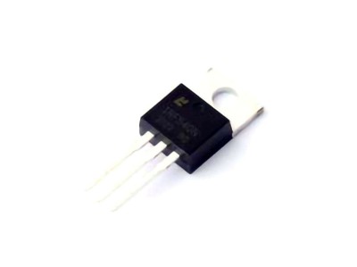
Introduction to the I RF B4115PBF MOSFET and Common Troubleshooting Scenarios
The Infineon (Infineon) IRFB4115PBF is a high-performance N-channel MOSFET (Metal-Oxide-Semiconductor Field-Effect Transistor) that is widely used in power electronics applications such as power supplies, motor drives, and audio amplifiers. Its low R_DS(on) (on-state resistance), high current handling capacity, and fast switching speed make it ideal for high-efficiency circuits. However, like all electronic components, it can experience failures or malfunctions over time due to a variety of factors.
In this section, we will first take a closer look at the characteristics and applications of the IRFB4115PBF. After that, we’ll explore some of the most common problems users face with this MOSFET and lay the groundwork for troubleshooting these issues effectively.
1.1 Understanding the IRFB4115PBF
Before diving into troubleshooting, it’s essential to understand the key features and specifications of the IRFB4115PBF. This N-channel MOSFET is designed to deliver excellent performance in high-speed switching applications. Here are some of its standout features:
Voltage Rating: The IRFB4115PBF has a maximum drain-to-source voltage (V_DSS) of 55V, making it suitable for low-voltage power supplies and other similar applications.
Current Rating: With a continuous drain current (I_D) of 120A, it can handle high loads with ease, which is essential in power-hungry circuits.
Low R_DS(on): This MOSFET boasts an ultra-low on-state resistance, typically around 0.004Ω, which reduces power losses and enhances efficiency in switching circuits.
Gate Threshold Voltage: The gate threshold voltage (V_GS(th)) is between 1V and 3V, allowing for easy integration with standard logic level signals.
Despite its impressive performance, like any component, the IRFB4115PBF is not immune to potential failures. Let's explore some common issues that users encounter with this MOSFET.
1.2 Common Issues with the IRFB4115PBF
1.2.1 Overheating and Thermal Runaway
One of the most frequent problems that users face when working with power MOSFETs , including the IRFB4115PBF, is overheating. When the MOSFET is driven too hard or does not have adequate cooling, it can enter thermal runaway. This occurs when an increase in temperature leads to an increase in power dissipation, which in turn causes more heating, leading to a vicious cycle.
Possible Causes:
Insufficient heat sinking or cooling.
Excessive current draw beyond the MOSFET’s rated specifications.
High ambient temperatures or poor ventilation.
Inadequate PCB design leading to poor heat dissipation.
Signs of Overheating:
MOSFET failure due to melting or physical damage.
Loss of functionality in the circuit.
A significant increase in temperature when the MOSFET is operating.
1.2.2 Gate Drive Issues
The IRFB4115PBF MOSFET requires proper gate drive voltage for efficient switching. If the gate is not driven adequately, the MOSFET may not turn on fully, leading to high R_DS(on) and excessive power loss. Insufficient gate voltage can also result in slow switching, which can create additional heating issues.
Possible Causes:
Incorrect gate drive voltage (V_GS).
Slow rise/fall times in the gate signal.
Gate driver circuit malfunction.
Incorrect gate resistor selection.
1.2.3 Short Circuit or Drain-Source Leakage
In certain cases, the MOSFET may fail internally, leading to a short circuit between the drain and source, or excessive leakage current. This can happen due to overvoltage conditions, excessive current, or physical damage to the MOSFET during handling or soldering.
Possible Causes:
Exceeding the MOSFET’s maximum drain-to-source voltage (V_DSS).
Excessive current draw beyond the rated drain current.
Physical damage to the MOSFET during soldering or assembly.
1.2.4 Switching Losses
While the IRFB4115PBF is designed for high-speed switching, improper switching characteristics or circuit design issues can lead to switching losses. These losses are typically associated with the transition periods when the MOSFET switches between on and off states. If the switching time is too slow or if there is a high gate charge, it can result in excess power dissipation and reduced efficiency.
Possible Causes:
Inadequate gate drive current.
Slow switching transitions.
High gate charge or large gate capacitance.
Troubleshooting Solutions and Best Practices for the IRFB4115PBF
In this second part, we will delve into detailed troubleshooting steps for the issues outlined in Part 1. We will also offer practical solutions to help you address these problems and maintain optimal performance of your IRFB4115PBF MOSFET.
2.1 Addressing Overheating and Thermal Runaway
To prevent overheating and thermal runaway, the following strategies can be implemented:
2.1.1 Improve Cooling
Ensuring the MOSFET has adequate cooling is critical. This can be achieved by:
Using a Heatsink: Attach an appropriate heatsink to the MOSFET to enhance heat dissipation.
Proper PCB Design: Ensure the PCB is designed with ample copper area around the MOSFET to spread the heat effectively. Additionally, place vias to conduct heat away from the component.
Active Cooling: In high-power applications, adding a fan or a cooling system can improve heat dissipation and prevent thermal overload.
2.1.2 Monitor Operating Conditions
Monitor the current and voltage conditions to ensure they stay within the rated specifications of the IRFB4115PBF. Utilize thermal sensors or infrared thermometers to check if the MOSFET is operating within safe thermal limits. If the current exceeds the rated capacity, consider using a MOSFET with a higher current rating.
2.1.3 Enhance Ventilation
In cases where the MOSFET is used in enclosed or poorly ventilated spaces, improving airflow around the component can help to dissipate heat. Ensure that the overall system design allows for sufficient ventilation, particularly in power electronics applications.
2.2 Solving Gate Drive Issues
If the gate voltage is not within the correct range or the switching is slow, the following actions should be taken:
2.2.1 Ensure Proper Gate Drive Voltage
The IRFB4115PBF requires a gate-source voltage (V_GS) of at least 10V for full enhancement (turn-on). Ensure the gate driver is capable of delivering this voltage consistently. If the MOSFET is not fully turning on, consider using a gate driver with higher current capability to drive the gate more effectively.
2.2.2 Use Proper Gate Resistors
Using the correct gate resistor value is crucial to prevent excessive switching losses. Too large a resistor can slow down the switching, while too small a resistor can cause excessive current spikes. Refer to the MOSFET's datasheet for the recommended gate resistor value based on the desired switching frequency.
2.2.3 Check Gate Driver Circuit
Inspect the gate driver circuit for issues such as malfunctioning components, poor grounding, or incorrect drive signals. A faulty gate driver can lead to poor switching performance, including excessive rise/fall times and heating.
2.3 Troubleshooting Drain-Source Leakage and Short Circuits
If you notice a short circuit or excessive leakage between the drain and source, take the following steps:
2.3.1 Check for Overvoltage Conditions
Ensure that the voltage across the MOSFET does not exceed the maximum rated V_DSS. If the voltage is too high, the MOSFET may fail catastrophically. Consider using a clamping circuit or a voltage regulator to prevent overvoltage situations.
2.3.2 Inspect for Physical Damage
Examine the MOSFET for signs of physical damage, such as burns, cracks, or discoloration, which could indicate a short circuit or breakdown of the MOSFET’s internal structure. If the MOSFET is damaged, replace it with a new one.
2.3.3 Test with a Multimeter
Use a multimeter to measure the resistance between the drain and source. A low resistance indicates a short, while a high resistance typically indicates proper operation. If a short is detected, replace the MOSFET.
2.4 Reducing Switching Losses
To minimize switching losses and enhance efficiency, implement the following strategies:
2.4.1 Improve Gate Drive Current
Ensure that the gate driver can supply sufficient current to charge and discharge the gate capacitance quickly. A higher gate drive current reduces the time the MOSFET spends in the transition region, minimizing switching losses.
2.4.2 Optimize Switching Frequency
Selecting the optimal switching frequency is crucial to minimizing losses. High switching frequencies can lead to excessive losses due to gate charge requirements and parasitic elements. Experiment with different frequencies to find the optimal balance between switching speed and efficiency.
2.4.3 Minimize Parasitic Inductances
Minimize parasitic inductances in the circuit by optimizing layout, particularly in the gate drive and source paths. Use short and wide PCB traces to reduce parasitic inductance, which can cause voltage spikes and delays during switching.
Conclusion
The IRFB4115PBF is a versatile and reliable MOSFET, but like any electronic component, it requires proper design and maintenance to operate at its best. By understanding common issues such as overheating, gate drive problems, leakage, and switching losses, and by implementing effective troubleshooting techniques, you can ensure the long-term reliability and efficiency of your systems. With the right knowledge and tools, you can keep your IRFB4115PBF MOSFETs performing optimally in any application.
Partnering with an electronic components supplier sets your team up for success, ensuring the design, production, and procurement processes are quality and error-free.
